
Creating Physically Based Materials - 2019.3
Tutorial
Beginner
+10XP
10m
(180)
Unity Technologies
The Unity Editor uses Physically Based Rendering (PBR) in order to more accurately simulate realistic lighting scenarios. To fully take advantage of PBR, a material should be physically based. This is done through the Shader — the script that mathematically calculates how a material should appear under different lighting conditions. In this tutorial, you will learn about standard Shaders and texture properties.
Languages available:
1. Creating Physically Based Materials
If you are using Unity 2018.2 or below, click here. If you are using Unity 2018.4, click here. If you are using Unity 2019.1 or 2019.2, click here.
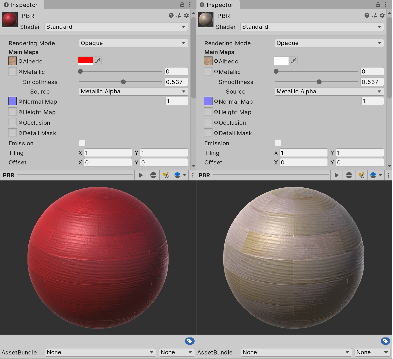
The Unity Editor uses Physically Based Rendering (PBR) to more accurately simulate realistic lighting scenarios. To fully take advantage of PBR, a Material should be physically based. This is done through the Shader — the script that calculates how a Material should appear under different lighting conditions. The user configures the Material with Textures and other value adjustments (Figure 01).
The Unity Standard Shader follows this format and is designed to work well with minimal set up. To read more about Physically Based Rendering and how the Standard Shader is used, refer to: Working with Physically-Based Shading: a Practical Approach.
There are two Shader options associated with the standard Material: Standard and Standard (Specular setup). Roughness and Specular setups are generally selected if the Textures being used with the Material were generated using a specific workflow in an outside Digital Content Creator (DCC). For example, if your Textures include a roughness map, then you should use the Roughness setup. If there is a specular map, then use the Specular setup. If a map is not present, use the standard Shader.
- In the Project window, right-click and select Create > Material.
- Give the Material a descriptive name based on how it will be used.
- At the top of the Inspector, select the Shader type that aligns with the Textures you will be using (Figure 02).
- Apply Texture maps to the appropriate Texture channels by clicking on the small radio button to the right of the Texture swatch and selecting it from the list (Figure 03).
Depending on the Shader you select, some Texture channels also allow a color overlay. These channels will have a color swatch option to the right of the Texture map channel (Figure 04).
2. Texture Properties
Albedo: Represents pure color information on the Material without any shadowing or lighting.
Metallic (appears in Standard and Standard (Roughness setup): Similar to the Specular Material below, Metallic represents how the surface of the Material reacts to light sources.
Specular (appears in Standard (Specular setup)): Represents the strength, color, and light source reflections that should appear on the Material. This is often thought of as how smooth an object is; the smoother the object appears, the more dramatic its specularity.
Smoothness: Represents how smooth the Material is. This controls how the light is spread across the surface of the Material.
Normal: Simulates a more detailed surface by faking height and depth information. Unlike a height map, which can only specify whether a surface appears to push up or down from the base level surface in a single axis, Normal maps are able to simulate depth and height from each axis so that the effect is believable from any viewing angle.
Height: Commonly used in conjunction with a Normal map, this simulates height and depth information based on camera position. A Material with a height map assigned will appear to have occluding surface details. This is achieved by exaggerating the map details that are closer to the camera, while reducing the details that are farther away (Figure 05).
Occlusion: Also referred to as the Ambient Occlusion (AO) map, it represents surfaces on the Material that would be naturally self-shadowed or otherwise appear darker than the rest of the surface. Example: A deep crack in a wooden board.
Detail Mask: Used in conjunction with the Secondary Detail Albedo and Secondary Normal Map. Detail Mask allows only certain areas to receive secondary mapping information.
Emission (appears if Emission box is checked): Defines sections of the Material that should glow and what color the glow should be. Intensity can be adjusted by manipulating the color overlay swatch associated with this channel. Note that light produced by an Emissive Material will only be visible on objects that are marked as Lightmap Static.
Secondary Detail Albedo: Overlays a secondary Albedo Texture map on top of the main Albedo map. This allows Materials to have extra surface color information. The Secondary Detail Albedo functions exactly the same as the main Albedo map, but is more expensive to render than a Material with just a single Albedo.
Secondary Normal Map: Overlays a secondary normal Texture map on top of the main normal map. This allows the Material to have extra surface information. An example of the Secondary Normal Map’s use would be the application of a tiling pore normal map for a character’s face.