
Editor Scripting
Tutorial
intermediate
+10XP
90 mins
(279)
Unity Technologies
Editor Scripting can help you customize and extend the Unity editor to make it easier to use on your projects. This tutorial covers the basics of editor scripting, including building custom inspectors, gizmos, and other Editor windows.
Languages available:
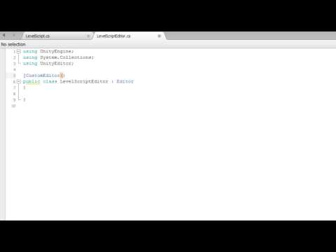
1. Building a Custom Inspector
Custom inspectors allow you to add a lot of power and flexibility to your workflow. In this video you will learn about the benefits of custom inspectors as well as how to build them.
LevelScript
using UnityEngine;
using System.Collections;

public class LevelScript : MonoBehaviour
{
    public int experience;

    public int Level
    {
        get { return experience / 750; }
    }
}
LevelScriptEditor
using UnityEngine;
using System.Collections;
using UnityEditor;

[CustomEditor(typeof(LevelScript))]
public class LevelScriptEditor : Editor
{
    public override void OnInspectorGUI()
    {
        LevelScript myTarget = (LevelScript)target;

        myTarget.experience = EditorGUILayout.IntField("Experience", myTarget.experience);
        EditorGUILayout.LabelField("Level", myTarget.Level.ToString());
    }
}
2. The DrawDefaultInspector Function
The DrawDefaultInspector function allows us to easily recreate the default inspector for a script inside a custom inspector. This is very useful if we only want to add new items to the inspector for a script instead of changing the currently existing items. In this video you will learn how to use the DrawDefaultInspector function.
SomeScript
using UnityEngine;
using System.Collections;
using UnityEditor;

public class SomeScript : MonoBehaviour
{
    public int level;
    public float health;
    public Vector3 target;
}
SomeScriptEditor
using UnityEngine;
using System.Collections;
using UnityEditor;

[CustomEditor(typeof(SomeScript))]
public class SomeScriptEditor : Editor
{
    public override void OnInspectorGUI()
    {
        DrawDefaultInspector();

        EditorGUILayout.HelpBox("This is a help box", MessageType.Info);
    }
}
3. Adding Buttons to a Custom Inspector
In Unity we can add buttons to editor windows so that we can call our functions from our scripts. Doing so give us the ability to write scripts specifically to improve our workflow. In this video you will learn how to create buttons in a custom inspector and how to tie them to functions that exist in our scripts.
ObjectBuilderScript
using UnityEngine;
using System.Collections;

public class ObjectBuilderScript : MonoBehaviour
{
    public GameObject obj;
    public Vector3 spawnPoint;


    public void BuildObject()
    {
        Instantiate(obj, spawnPoint, Quaternion.identity);
    }
}
ObjectBuilderEditor
using UnityEngine;
using System.Collections;
using UnityEditor;

[CustomEditor(typeof(ObjectBuilderScript))]
public class ObjectBuilderEditor : Editor
{
    public override void OnInspectorGUI()
    {
        DrawDefaultInspector();

        ObjectBuilderScript myScript = (ObjectBuilderScript)target;
        if(GUILayout.Button("Build Object"))
        {
            myScript.BuildObject();
        }
    }
}
4. Unity Editor Extensions – Menu Items
The Unity editor allows adding custom menus that look and behave like the built-in menus. This can be very useful for adding commonly used functionality that is frequently needed to be accessible directly from the editor UI.
In this lesson I’ll show how new menu items in the Unity editor are created and try to provide real-world example usages to every described topic.
Adding Menu Items
In order to add a new menu to the top-level toolbar, you should create an editor script (a script file that is placed anywhere in the project under a folder named Editor). Menu items are created in script code as static methods that are marked with the MenuItem attribute.
For example, it’s common to add a new “Tools” menu (or a top-level menu with your company’s name) to provide options that are commonly used by your team/company.
Here’s an example of adding a new Tools menu with an option under it (clears all PlayerPrefs data):
using UnityEngine;
using UnityEditor;

public class MenuItems
{
    [MenuItem("Tools/Clear PlayerPrefs")]
    private static void NewMenuOption()
    {
        PlayerPrefs.DeleteAll();
    }
}
This creates a new editor menu called Tools, and places a menu item called Clear PlayerPrefs under it:
It’s also possible to create new menu items under an existing menu (e.g: under the Window menu), and also to create multiple levels of menus for better structuring and organization (recommended):
using UnityEngine;
using UnityEditor;

public class MenuItemsExample
{
    // Add a new menu item under an existing menu

    [MenuItem("Window/New Option")]
    private static void NewMenuOption()
    {
    }

    // Add a menu item with multiple levels of nesting

    [MenuItem("Tools/SubMenu/Option")]
    private static void NewNestedOption()
    {
    }
}
This results in the following menu items:
Hotkeys
To allow power users and keyboard junkies to work faster, new menu items can be assigned with hotkeys – shortcut key combinations that will automatically launch them.
These are the supported keys (can also be combined together):
- % – CTRL on Windows / CMD on OSX
- # – Shift
- & – Alt
- LEFT/RIGHT/UP/DOWN – Arrow keys
- F1…F2 – F keys
- HOME, END, PGUP, PGDN
Character keys not part of a key-sequence are added by adding an underscore prefix to them (e.g: _g for shortcut key “G”).
Hotkey character combinations are added to the end of the menu item path, preceded by a space), as shown in the following examples:
// Add a new menu item with hotkey CTRL-SHIFT-A

[MenuItem("Tools/New Option %#a")]
private static void NewMenuOption()
{
}

// Add a new menu item with hotkey CTRL-G

[MenuItem("Tools/Item %g")]
private static void NewNestedOption()
{
}

// Add a new menu item with hotkey G
[MenuItem("Tools/Item2 _g")]
private static void NewOptionWithHotkey()
{
}
Menu items with hotkeys will display the key-combination that is used to launch them. For example, the code above results in this menu:
Note: There’s no validation for overlapping hotkeys ! defining multiple menu items with the same hotkey results in only 1 option being called by hitting the key combination.
Special Paths
As seen, the path passed to the MenuItem attribute controls under which top level menu the new item will be placed.
Unity has a few “special” paths that act as context menus (menus that are accessible using right-click):
- Assets – items will be available under the “Assets” menu, as well using right-click inside the project view.
- Assets/Create – items will be listed when clicking on the “Create” button in the project view (useful when adding new types that can be added to the project)
- CONTEXT/ComponentName – items will be available by right-clicking inside the inspector of the given component.
Here are some examples of how to use these special paths:
// Add a new menu item that is accessed by right-clicking on an asset in the project view

[MenuItem("Assets/Load Additive Scene")]
private static void LoadAdditiveScene()
{
    var selected = Selection.activeObject;
    EditorApplication.OpenSceneAdditive(AssetDatabase.GetAssetPath(selected));
}

// Adding a new menu item under Assets/Create

[MenuItem("Assets/Create/Add Configuration")]
private static void AddConfig()
{
    // Create and add a new ScriptableObject for storing configuration
}

// Add a new menu item that is accessed by right-clicking inside the RigidBody component

[MenuItem("CONTEXT/Rigidbody/New Option")]
private static void NewOpenForRigidBody()
{
}
The results for this code segment is these new menu options:
Assets (project view) right-click menu
New option available from the Asset’s CREATE button
New context menu option for the RigidBody component
Validation
Some menu items only make sense in a given context, and should not be available otherwise. Enabling/disabling menu items according to their usage context is done by adding validation methods.
Validation methods are static methods, marked with the MenuItem attribute, passing true to the validation argument.
The validation method should have the same menu path as the menu it is validating, and should return a boolean value to determine whether the menu item is active or not.
For example, Validation methods can be used to add a right-click menu to Texture assets only under the project view:
[MenuItem("Assets/ProcessTexture")]
private static void DoSomethingWithTexture()
{
}

// Note that we pass the same path, and also pass "true" to the second argument.
[MenuItem("Assets/ProcessTexture", true)]
private static bool NewMenuOptionValidation()
{
    // This returns true when the selected object is a Texture2D (the menu item will be disabled otherwise).
    return Selection.activeObject.GetType() == typeof(Texture2D);
}
When right-clicking on anything that is not a texture in the project view, the menu item option will be disabled (greyed out):
Controlling Order with Priority
Priority is a number that can be assigned to a menu item (passed to the MenuItem attribute) that controls the ordering of menu items under the root menu.
Menu items are also automatically grouped according to their assigned priority in increments of 50:
[MenuItem("NewMenu/Option1", false, 1)]
private static void NewMenuOption()
{
}

[MenuItem("NewMenu/Option2", false, 2)]
private static void NewMenuOption2()
{
}

[MenuItem("NewMenu/Option3", false, 3)]
private static void NewMenuOption3()
{
}

[MenuItem("NewMenu/Option4", false, 51)]
private static void NewMenuOption4()
{
}

[MenuItem("NewMenu/Option5", false, 52)]
private static void NewMenuOption5()
{
}
The code example results in the menu that has 2 groups of items, according to the assigned priority:
If it is required to add and organize menu items under existing Unity menus, a bit of “guess work” is needed, as most of the built-in menu items use priorities. Another option is to use a tool such as Reflector and look at the source code for internal Unity code (such as UnityEditor.CreateBuildInWindows) that is responsible for creating some of the menus in the editor.
Related Classes
Below is a listing of a few extra classes that are related to adding new menu items.
#MenuCommand#
When adding a new menu item to an inspector (using “CONTEXT/Component”, as described above), sometimes it is necessary to get a reference to the actual component (e.g: to modify its data).
This can be done by adding a MenuCommand argument to the static method that defines the new menu item:
[MenuItem("CONTEXT/Rigidbody/New Option")]
private static void NewMenuOption(MenuCommand menuCommand)
{
    // The RigidBody component can be extracted from the menu command using the context field.
    var rigid = menuCommand.context as Rigidbody;
}
As seen in the code example, when invoking the menu item, the component that serves as its context can be accessed using the context field.
#ContextMenu#
This attribute allows defining context menu items. This works exactly the same as defining a method with the MenuItem attribute with a path that starts with “CONTEXT/…”.
The difference is that with this attribute, you define the default context menu for a given component, whereas with the MenuItem approach, you “extend” other components’ menus (for example – the default components that are part of the engine).
Example – a component that exposes a context menu option to clear its data:
public class NameBehaviour : MonoBehaviour
{
    public string Name;

    [ContextMenu("Reset Name")]
    private static void ResetName()
    {
        Name = string.Empty;
    }
}
#ContextMenuItem#
This attribute is added to fields of a component (MonoBehaviour) class, to allow adding context menus at a finer resolution. While the ContextMenu attribute shown above adds context menus at the component level, marking fields with this attribute will add a right-click menu to individual public fields.
Since this attribute is added to a field and not a method, it accepts 2 arguments: the display name of the menu item and a name of a method (instance method) to be invoked when the menu item is selected.
Example – Adding a method to randomly initialize a component’s field to some state:
public class NameBehaviour : MonoBehaviour
{
    [ContextMenuItem("Randomize Name", "Randomize")]
    public string Name;

    private void Randomize()
    {
        Name = "Some Random Name";
    }
}
This code results in this context menu when right-clicking on the Name field of this component:
Wrap Up
As shown in this article, extending the Unity editor with custom menus can be pretty straightforward.
Building commonly used functionality and having it available from the editor is recommended for teams of all sizes and can be a huge time saver.
5. An Introduction to Editor Scripting
You can use editor scripting inside Unity to make life easier for your game designers, or even yourself. With a small amount of code, you can automate some of the more tedious aspects of using the inspector to configure your behaviours, and provide visual feedback on configuration changes. We will create a simple projectile and launcher system to demonstrate some of the basics that can be achieved by scripting the editor.
In this tutorial:
- How to expose methods in the Inspector
- How to use Handles to create custom Gizmos
- How to use field attributes to customise the Inspector
Get Started with Simple Techniques
We start with a basic projectile class, which lets the user assign to the rigidbody field, which provides the Physics behaviour. We will then extend this class to make it easier to use.
public class Projectile : MonoBehaviour
{
    public Rigidbody rigidbody;
}
When you add the above component to a GameObject, you will need to also add a Rigidbody component. We can make this happen automatically by using a RequireComponent attribute which will automatically add the Rigidbody component (if it doesn’t already exist) when the Projectile component is first added to a GameObject.
[RequireComponent(typeof(Rigidbody))]
public class Projectile : MonoBehaviour
{
    public Rigidbody rigidbody;
}
Let’s make it even better, by auto-assigning the Rigidbody component to the rigidbody field at the same time. We do this using the Reset method, which is called when you first add the component to a GameObject. You can also call the Reset method manually by right clicking the component header in the inspector, and choosing the ‘Reset’ menu item.
[RequireComponent(typeof(Rigidbody))]
public class Projectile : MonoBehaviour
{
    public Rigidbody rigidbody;
    void Reset()
    {
        rigidbody = GetComponent<Rigidbody>();
    }
}
Finally, we can minimise the valuable screen space taken up the inspector GUI, by hiding the rigidbody field using a HideInInspector attribute. We can also remove editor warnings by using the ‘new’ keyword on the field declaration.
[RequireComponent(typeof(Rigidbody))]
public class Projectile : MonoBehaviour
{
    [HideInInspector] new public Rigidbody rigidbody;
    void Reset()
    {
        rigidbody = GetComponent<Rigidbody>();
    }
}
These are very simple techniques you can use on all your components to keep things clean and tidy, and minimise configuration mistakes.
Simple Inspector Customisation
The next class we look at is the Launcher class. It instantiates a new Projectile and modifies the velocity so that it shoots forward at a specified velocity. (It will actually launch any prefab with a RigidBody component.)
public class Launcher : MonoBehaviour
{
    public Rigidbody projectile;
    public Vector3 offset = Vector3.forward;
    public float velocity = 10;

    public void Fire()
    {
        var body = Instantiate(
            projectile,
            transform.TransformPoint(offset),
            transform.rotation);
        body.velocity = Vector3.forward * velocity;
    }
}
The first thing we can add is a Range attribute to the ‘velocity’ field which creates a slider in the inspector GUI. The designer can then quickly slide this value around to experiment with different velocities, or type in an exact figure. We also add a ContextMenu attribute to the ‘Fire’ method, which allows us to run the method by right clicking the component header in the inspector. You can do this with any method (as long as it has zero arguments) to add editor functionality to your component.
public class Launcher : MonoBehaviour
{
    public Rigidbody projectile;
    public Vector3 offset = Vector3.forward;
    [Range(0, 100)] public float velocity = 10;

    [ContextMenu("Fire")]
    public void Fire()
    {
        var body = Instantiate(
            projectile,
            transform.TransformPoint(offset),
            transform.rotation);
        body.velocity = Vector3.forward * velocity;
    }
}
To take this example further, we need to write a Editor class to extend the editor functionality of the Launcher component. The class has a CustomEditor attribute which tells Unity which component this custom editor is used for. The OnSceneGUI method is called when the scene view is rendered, allowing us to draw widgets inside the scene view. As this is an Editor class, it must be inside a folder named ‘Editor’ somewhere in your project.
using UnityEditor;

[CustomEditor(typeof(Launcher))]
public class LauncherEditor : Editor
{
    void OnSceneGUI()
    {
        var launcher = target as Launcher;
    }
}
Lets add to the OnSceneGUI method so that we can have a widget which allows us to display and adjust the offset position inside the scene view. Because the offset is stored relative to the parent transform, we need to use the Transform.InverseTransformPoint and Transform.TransformPoint methods to convert the offset position into world space for use by the Handles.PositionHandle method, and back to local space for storing in the offset field.
using UnityEditor;

[CustomEditor(typeof(Launcher))]
public class LauncherEditor : Editor
{
    void OnSceneGUI()
    {
        var launcher = target as Launcher;
        var transform = launcher.transform;
        launcher.offset = transform.InverseTransformPoint(
            Handles.PositionHandle(
                transform.TransformPoint(launcher.offset),
                transform.rotation));
    }
}
We can also create a custom Projectile editor class. Let's add a damageRadius field to the Projectile class, which could be used in the game code to calculate which other GameObjects might be affected by the projectile.
[RequireComponent(typeof(Rigidbody))]
public class Projectile : MonoBehaviour
{
    [HideInInspector] new public Rigidbody rigidbody;
    public float damageRadius = 1;

    void Reset()
    {
        rigidbody = GetComponent<Rigidbody>();
    }
}
We might be tempted to add a simple Range attribute to the damageRadius field, however we can do better by visualising this field in the scene view. We create another Editor class for the Projectile component, and use a Handles.RadiusHandle to visualise the field, and allow it to be adjusted in the scene view.
using UnityEditor;

[CustomEditor(typeof(Projectile))]
public class ProjectileEditor : Editor
{
    void OnSceneGUI()
    {
        var projectile = target as Projectile;
        var transform = projectile.transform;
        projectile.damageRadius = Handles.RadiusHandle(
            transform.rotation,
            transform.position,
            projectile.damageRadius);
    }
}
We should also add a Gizmo so we can see the Projectile in the scene view when it has no renderable geometry. Here we have used a DrawGizmo attribute to specify a method which is used to draw the gizmo for the Projectile class. This can also be done by implementing OnDrawGizmos and OnDrawGizmosSelected in the Projectile class itself, however it is better practice to keep editor functionality separated from game functionality when possible, so we use the DrawGizmo attribute instead.
using UnityEditor;
using UnityEngine;

[CustomEditor(typeof(Projectile))]
public class ProjectileEditor : Editor
{
    [DrawGizmo(GizmoType.Selected | GizmoType.NonSelected)]
    static void DrawGizmosSelected(Projectile projectile, GizmoType gizmoType)
    {
        Gizmos.DrawSphere(projectile.transform.position, 0.125f);
    }

    void OnSceneGUI()
    {
        var projectile = target as Projectile;
        var transform = projectile.transform;
        projectile.damageRadius = Handles.RadiusHandle(
            transform.rotation,
            transform.position,
            projectile.damageRadius);
    }
}
Widgets in the Scene View
We can also use Editor IMGUI methods inside OnSceneGUI, to create any kind of scene view editor control. We are going to expose the Fire method of the Launcher component using a button inside the scene view. We calculate a screen space rect right next to the offset world position where we want to draw the GUI. Also, we don’t want to call Fire during edit mode, only when the game is playing, so we wrap Fire method call in a EditorGUI.DisabledGroupScope which will only enable the button when we are in Play mode.
using UnityEditor;

[CustomEditor(typeof(Launcher))]
public class LauncherEditor : Editor
{
    void OnSceneGUI()
    {
        var launcher = target as Launcher;
        var transform = launcher.transform;
        launcher.offset = transform.InverseTransformPoint(
            Handles.PositionHandle(
                transform.TransformPoint(launcher.offset),
                transform.rotation));
        Handles.BeginGUI();
        var rectMin = Camera.current.WorldToScreenPoint(
            launcher.transform.position +
            launcher.offset);
        var rect = new Rect();
        rect.xMin = rectMin.x;
        rect.yMin = SceneView.currentDrawingSceneView.position.height -
            rectMin.y;
        rect.width = 64;
        rect.height = 18;
        GUILayout.BeginArea(rect);
        using (new EditorGUI.DisabledGroupScope(!Application.isPlaying))
        {
            if (GUILayout.Button("Fire"))
                launcher.Fire();
        }
        GUILayout.EndArea();
        Handles.EndGUI();
    }
}
Physics in game design can be hard to debug, so let’s add a helper for the designer which displays an estimate of where the projectile will be after 1 second of flight time. We need the mass of the projectile to calculate this position, therefore we check that the rigidbody field is not null before attempting the calculation. We also draw a dotted line from the launcher object to the offset position for clarity (using Handles.DrawDottedLine), letting the designer know that this position handle is modifying the offset field, not the transform position. Let’s also add a label to the offset handle using Handles.Label.
This is done using a method with a DrawGizmo attribute, in the same way as the ProjectileEditor. We also add an Undo.RecordObject call, which, with the help of EditorGUI.ChangeCheckScope allows us to record an undo operation when the offset is changed. (If you haven’t seen the using statement before, you can read up on it at MSDN.)
using UnityEditor;

[CustomEditor(typeof(Launcher))]
public class LauncherEditor : Editor
{
    [DrawGizmo(GizmoType.Pickable | GizmoType.Selected)]
    static void DrawGizmosSelected(Launcher launcher, GizmoType gizmoType)
    {
        var offsetPosition = launcher.transform.position + launcher.offset;
        Handles.DrawDottedLine(launcher.transform.position, offsetPosition, 3);
        Handles.Label(offsetPosition, "Offset");
        if (launcher.projectile != null)
        {
            var endPosition = offsetPosition +
                (launcher.transform.forward *
                launcher.velocity /
                launcher.projectile.mass);
            using (new Handles.DrawingScope(Color.yellow))
            {
                Handles.DrawDottedLine(offsetPosition, endPosition, 3);
                Gizmos.DrawWireSphere(endPosition, 0.125f);
                Handles.Label(endPosition, "Estimated Position");
            }
        }
    }

    void OnSceneGUI()
    {
        var launcher = target as Launcher;
        var transform = launcher.transform;

            using (var cc = new EditorGUI.ChangeCheckScope())
            {
               var newOffset = transform.InverseTransformPoint(

               Handles.PositionHandle(
                   transform.TransformPoint(launcher.offset),
                   transform.rotation));

               if(cc.changed)
               {
                   Undo.RecordObject(launcher, "Offset Change");
                   launcher.offset = newOffset;
               }
           }

        Handles.BeginGUI();
        var rectMin = Camera.current.WorldToScreenPoint(
            launcher.transform.position +
            launcher.offset);
        var rect = new Rect();
        rect.xMin = rectMin.x;
        rect.yMin = SceneView.currentDrawingSceneView.position.height -
            rectMin.y;
        rect.width = 64;
        rect.height = 18;
        GUILayout.BeginArea(rect);
        using (new EditorGUI.DisabledGroupScope(!Application.isPlaying))
        {
            if (GUILayout.Button("Fire"))
                launcher.Fire();
        }
        GUILayout.EndArea();
        Handles.EndGUI();
    }
}
}
If you try this out in your editor, you will notice that the position estimate is not very accurate! Let's change the calculation to take gravity into account, and draw a curved path with Handles.DrawAAPolyLine and Gizmos.DrawWireSphere through the one second flight time trajectory. If we use Handles.DrawingScope to change the colour of the widgets, we don’t need to worry about setting it back to the previous handle colour when the method finishes.
[DrawGizmo(GizmoType.Pickable | GizmoType.Selected)]
static void DrawGizmosSelected(Launcher launcher, GizmoType gizmoType)
{
{
    var offsetPosition = launcher.transform.TransformPoint(launcher.offset);
    Handles.DrawDottedLine(launcher.transform.position, offsetPosition, 3);
    Handles.Label(offsetPosition, "Offset");
    if (launcher.projectile != null)
    {
        var positions = new List<Vector3>();
        var velocity = launcher.transform.forward *
            launcher.velocity /
            launcher.projectile.mass;
        var position = offsetPosition;
        var physicsStep = 0.1f;
        for (var i = 0f; i <= 1f; i += physicsStep)
        {
            positions.Add(position);
            position += velocity * physicsStep;
            velocity += Physics.gravity * physicsStep;
        }
        using (new Handles.DrawingScope(Color.yellow))
        {
            Handles.DrawAAPolyLine(positions.ToArray());
            Gizmos.DrawWireSphere(positions[positions.Count - 1], 0.125f);
            Handles.Label(positions[positions.Count - 1], "Estimated Position (1 sec)");
        }
    }
}
}
In Conclusion
These are some very simple ways you can improve the editor experience for other game designers and yourself. Using Editor.OnSceneGUI, you have the ability to create any kind of editor tool, right inside the scene view. It is definitely worthwhile becoming familiar with the Handles class and all the functionality it can provide you, helping you smooth out the game design and development process for yourself and your team.
6. Creating a Spline Tool
In this tutorial you will cover:
- How to use Height widgets in the scene view
- How SerializedProperty and SerializedObject instances are used to manipulate components
- How to implement a custom Inspector GUI
- How to respond to, intercept and use GUI events
- How to query internal Editor state to customise tool behaviour
Creating the Component
If we create an interface which specifies the API of our spline tool, we can use this interface instead of a concrete class, which allows us to switch between implementations, and integrate with any other systems which might arrive in the future, as long as they also use the interface.
This interface specification contains the general methods which are applicable across most spline algorithms. It contains methods for creating and adjusting the spline, and methods for querying the spline for different information.
The Spline Interface (ISpline.cs)
/// <summary>
/// A interface for general spline data.
/// NB: - All Vector3 arguments and Vector3 return values are in world space.
///     - All t arguments specify a uniform position along the spline, apart
///       from the GetNonUniformPoint method.
/// </summary>
public interface ISpline
{
    Vector3 GetNonUniformPoint(float t);
    Vector3 GetPoint(float t);


    Vector3 GetLeft(float t);
    Vector3 GetRight(float t);
    Vector3 GetUp(float t);
    Vector3 GetDown(float t);
    Vector3 GetForward(float t);
    Vector3 GetBackward(float t);


    float GetLength(float stepSize);


    Vector3 GetControlPoint(int index);
    void SetControlPoint(int index, Vector3 position);
    void InsertControlPoint(int index, Vector3 position);
    void RemoveControlPoint(int index);


    Vector3 GetDistance(float distance);
    Vector3 FindClosest(Vector3 worldPoint);


    int ControlPointCount { get; }
}
An empty class. (SplineComponent.cs)
If we use a default implementation of the class, we will get the following class. It does nothing in itself, but gives us stubs to enter all the required methods to satisfy the ISpline interface.
public class SplineComponent : MonoBehaviour, ISpline
{
    public int ControlPointCount { get { throw new System.NotImplementedException(); } }


    public Vector3 FindClosest(Vector3 worldPoint)
    {
        throw new System.NotImplementedException();
    }


    public Vector3 GetBackward(float t)
    {
        throw new System.NotImplementedException();
    }


    public Vector3 GetControlPoint(int index)
    {
        throw new System.NotImplementedException();
    }


    public Vector3 GetDistance(float distance)
    {
        throw new System.NotImplementedException();
    }


    public Vector3 GetDown(float t)
    {
        throw new System.NotImplementedException();
    }


    public Vector3 GetForward(float t)
    {
        throw new System.NotImplementedException();
    }


    public Vector3 GetLeft(float t)
    {
        throw new System.NotImplementedException();
    }


    public float GetLength(float stepSize)
    {
        throw new System.NotImplementedException();
    }


    public Vector3 GetNonUniformPoint(float t)
    {
        throw new System.NotImplementedException();
    }


    public Vector3 GetPoint(float t)
    {
        throw new System.NotImplementedException();
    }


    public Vector3 GetRight(float t)
    {
        throw new System.NotImplementedException();
    }


    public Vector3 GetUp(float t)
    {
        throw new System.NotImplementedException();
    }


    public void InsertControlPoint(int index, Vector3 position)
    {
        throw new System.NotImplementedException();
    }


    public void RemoveControlPoint(int index)
    {
        throw new System.NotImplementedException();
    }


    public void SetControlPoint(int index, Vector3 position)
    {
        throw new System.NotImplementedException();
    }
}
The Interpolator
This is a hermite spline interpolation function. It takes 4 vectors (a and d are control points, b and c are the start and end points) and a u parameter which specifies the interpolation position.
    internal static Vector3 Interpolate(Vector3 a, Vector3 b, Vector3 c, Vector3 d, float u)
    {
        return (
            0.5f *
            (
                (-a + 3f * b - 3f * c + d) *
                (u * u * u) +
                (2f * a - 5f * b + 4f * c - d) *
                (u * u) +
                (-a + c) *
                u + 2f * b
            )
        );
    }
The Data
We need some fields to store that data used by our Interpolate function. The closed field specifies if the spline should form a closed loop or not, the points list will contain our control points which specify the shape of the spline, and finally the length is a nullable float where we can store the length of the spline once it has been calculated? Why nullable? You will find out soon!
    public bool closed = false;
    public List<Vector3> points = new List<Vector3>();
    public float? length;
We can now fill in the body of some of the methods required by the interface.
    public int ControlPointCount => points.Count;


    public Vector3 GetNonUniformPoint(float t)
    {
        switch (points.Count)
        {
            case 0:
                return Vector3.zero;
            case 1:
                return transform.TransformPoint(points[0]);
            case 2:
                return transform.TransformPoint(Vector3.Lerp(points[0], points[1], t));
            case 3:
                return transform.TransformPoint(points[1]);
            default:
                return Hermite(t);
        }
    }

    public void InsertControlPoint(int index, Vector3 position)
    {
        ResetIndex();
        if (index >= points.Count)
            points.Add(position);
        else
            points.Insert(index, position);
    }


    public void RemoveControlPoint(int index)
    {
        ResetIndex();
        points.RemoveAt(index);
    }


    public Vector3 GetControlPoint(int index)
    {
        return points[index];
    }


    public void SetControlPoint(int index, Vector3 position)
    {
        ResetIndex();
        points[index] = position;
    }
This is the function which looks up the correct control points for a position along the spline then performs and return the interpolated world position.
    Vector3 Hermite(float t)
    {
        var count = points.Count - (closed ? 0 : 3);
        var i = Mathf.Min(Mathf.FloorToInt(t * (float)count), count - 1);
        var u = t * (float)count - (float)i;
        var a = GetPointByIndex(i);
        var b = GetPointByIndex(i + 1);
        var c = GetPointByIndex(i + 2);
        var d = GetPointByIndex(i + 3);
        return transform.TransformPoint(Interpolate(a, b, c, d, u));
    }

    Vector3 GetPointByIndex(int i)
    {
        if (i < 0) i += points.Count;
        return points[i % points.Count];
    }
How to get Uniform points along a spline? (SplineIndex.cs)
If we look at the interface documentation, you will notice that almost all the query methods are expected to return a uniform position along the spline. This is not straightforward, as our spline is composed of arbitrary control points which could be any distance from each other. In addition to this, the nature of our interpolation algorithm means we cannot simply store the distance between control points and use that to modify the t parameter.
Therefore, we create an index of discrete, uniform positions along the spline. This index is then used to provide the uniform positions assumed by the interface.
public class SplineIndex
{
    public Vector3[] linearPoints;
    SplineComponent spline;


    public int ControlPointCount => spline.ControlPointCount;


    public SplineIndex(SplineComponent spline)
    {
        this.spline = spline;
        ReIndex();
    }


    public void ReIndex()
    {
        var searchStepSize = 0.00001f;
        var length = spline.GetLength(searchStepSize);
        var indexSize = Mathf.FloorToInt(length * 2);
        var _linearPoints = new List<Vector3>(indexSize);
        var t = 0f;


        var linearDistanceStep = length / 1024;
        var linearDistanceStep2 = Mathf.Pow(linearDistanceStep, 2);


        var start = spline.GetNonUniformPoint(0);
        _linearPoints.Add(start);
        while (t <= 1f)
        {
            var current = spline.GetNonUniformPoint(t);
            while ((current - start).sqrMagnitude <= linearDistanceStep2)
            {
                t += searchStepSize;
                current = spline.GetNonUniformPoint(t);
            }
            start = current;
            _linearPoints.Add(current);
        }
        linearPoints = _linearPoints.ToArray();
    }


    public Vector3 GetPoint(float t)
    {
        var sections = linearPoints.Length - (spline.closed ? 0 : 3);
        var i = Mathf.Min(Mathf.FloorToInt(t * (float)sections), sections - 1);
        var count = linearPoints.Length;
        if (i < 0) i += count;
        var u = t * (float)sections - (float)i;
        var a = linearPoints[(i + 0) % count];
        var b = linearPoints[(i + 1) % count];
        var c = linearPoints[(i + 2) % count];
        var d = linearPoints[(i + 3) % count];
        return SplineComponent.Interpolate(a, b, c, d, u);
    }
}
Add lazy indexing to Spline
The index we have created is expensive to create, and takes (relatively speaking) quite a lot of memory. If the user does not need this index, we should avoid creating it. This is achieved by using a private property which will only create an index when required, then re-use that index. We also provide a method to reset the index, so that the index will be rebuilt when control points or other parameters are changed.
The index now allows us to add a body to the GetPoint method required by the interface, and return a uniform position along the spline.
    /// <summary>
    /// Index is used to provide uniform point searching.
    /// </summary>
    SplineIndex uniformIndex;
    SplineIndex Index
    {
        get
        {
            if (uniformIndex == null) uniformIndex = new SplineIndex(this);
            return uniformIndex;
        }
    }

    public void ResetIndex()
    {
        uniformIndex = null;
        length = null;
    }

    public Vector3 GetPoint(float t) => Index.GetPoint(t);
Add Query Methods
Now that we have an implementation for GetPoint, we can construct the remainder of the query methods.
    public Vector3 GetRight(float t)
    {
        var A = GetPoint(t - 0.001f);
        var B = GetPoint(t + 0.001f);
        var delta = (B - A);
        return new Vector3(-delta.z, 0, delta.x).normalized;
    }


    public Vector3 GetForward(float t)
    {
        var A = GetPoint(t - 0.001f);
        var B = GetPoint(t + 0.001f);
        return (B - A).normalized;
    }


    public Vector3 GetUp(float t)
    {
        var A = GetPoint(t - 0.001f);
        var B = GetPoint(t + 0.001f);
        var delta = (B - A).normalized;
        return Vector3.Cross(delta, GetRight(t));
    }


    public Vector3 GetPoint(float t) => Index.GetPoint(t);


    public Vector3 GetLeft(float t) => -GetRight(t);


    public Vector3 GetDown(float t) => -GetUp(t);


    public Vector3 GetBackward(float t) => -GetForward(t);
For the same reasons we need to construct an index, we also need to iterate along the spline to get an estimate of the total length. The step paramter controls how accurate the estimate will be. It defaults to 0.001f, which is acceptable for most cases.
    public float GetLength(float step = 0.001f)
    {
        var D = 0f;
        var A = GetNonUniformPoint(0);
        for (var t = 0f; t < 1f; t += step)
        {
            var B = GetNonUniformPoint(t);
            var delta = (B - A);
            D += delta.magnitude;
            A = B;
        }
        return D;
    }

    public Vector3 GetDistance(float distance)
    {
        if (length == null) length = GetLength();
        return uniformIndex.GetPoint(distance / length.Value);
    }
The FindClosest method returns the approximate closest position on the spline to a world point. Due to the nature of splines, this solution cannot be analytical and we must create a numerical solution to solve the problem. The spline is divided into 1024 points and we choose the closest by comparing square of the distance to the world point.
    public Vector3 FindClosest(Vector3 worldPoint)
    {
        var smallestDelta = float.MaxValue;
        var step = 1f / 1024;
        var closestPoint = Vector3.zero;
        for (var i = 0; i <= 1024; i++)
        {
            var p = GetPoint(i * step);
            var delta = (worldPoint - p).sqrMagnitude;
            if (delta < smallestDelta)
            {
                closestPoint = p;
                smallestDelta = delta;
            }
        }
        return closestPoint;
    }
Add editor helper methods
The editor provides the Reset method, which is used to set default values on the component when it is first added to a gameobject. Add 4 default points as that is the minimum required for our spline implementation.
    void Reset()
    {
        points = new List<Vector3>() {
            Vector3.forward * 3,
            Vector3.forward * 6,
            Vector3.forward * 9,
            Vector3.forward * 12
        };
    }
OnValidate is called by the editor whenever values on the component have been changed. If we have an active index on our component, we reindex the spline so that the index will be built on the changed values.
    void OnValidate()
    {
        if (uniformIndex != null) uniformIndex.ReIndex();
    }
Creating the Editor
The SplineComponent works nicely, but to use it effectively inside the Unity Editor, we are going to need to make it much more user friendly.
A Custom Inspector (Editor/SplineComponentEditor.cs)
The first step is a custom inspector. This is created inside an Editor class via the OnInspectorGUI method. The method below sets up widgets for the component fields, and adds some buttons for some useful utility methods we will create later.
[CustomEditor(typeof(SplineComponent))]
public class SplineComponentEditor : Editor
{
    public override void OnInspectorGUI()
    {
        EditorGUILayout.HelpBox("Hold Shift and click to append and insert curve points. Backspace to delete points.", MessageType.Info);
        var spline = target as SplineComponent;
        GUILayout.BeginHorizontal();
        var closed = GUILayout.Toggle(spline.closed, "Closed", "button");
        if (spline.closed != closed)
        {
            spline.closed = closed;
            spline.ResetIndex();
        }
        if (GUILayout.Button("Flatten Y Axis"))
        {
            Undo.RecordObject(target, "Flatten Y Axis");
            //TODO: Flatten(spline.points);
            spline.ResetIndex();
        }
        if (GUILayout.Button("Center around Origin"))
        {
            Undo.RecordObject(target, "Center around Origin");
            //TODO: CenterAroundOrigin(spline.points);
            spline.ResetIndex();
        }
        GUILayout.EndHorizontal();
    }
}
Draw Gizmos
Gizmos are the visual inside the scene view that helps us identify the component, especially since it has no renderable geometry. There are 3 functions, the main drawing function (DrawGizmo) and 2 other functions which have the DrawGizmo attribute. This allows us to draw a high resolution gizmo when the spline component is selected in the hierarchy, and a low resolution gizmo at other times.
    [DrawGizmo(GizmoType.NonSelected)]
    static void DrawGizmosLoRes(SplineComponent spline, GizmoType gizmoType)
    {
        Gizmos.color = Color.white;
        DrawGizmo(spline, 64);
    }

    [DrawGizmo(GizmoType.Selected)]
    static void DrawGizmosHiRes(SplineComponent spline, GizmoType gizmoType)
    {
        Gizmos.color = Color.white;
        DrawGizmo(spline, 1024);
    }

    static void DrawGizmo(SplineComponent spline, int stepCount)
    {
        if (spline.points.Count > 0)
        {
            var P = 0f;
            var start = spline.GetNonUniformPoint(0);
            var step = 1f / stepCount;
            do
            {
                P += step;
                var here = spline.GetNonUniformPoint(P);
                Gizmos.DrawLine(start, here);
                start = here;
            } while (P + step <= 1);
        }
    }
Scene View Controls
You will notice that we didn’t create inspector fields for the spline control points. That is because we are going to manage the control points through the scene view.
These two fields store the index of the currently selected control point, and if we choose to remove a control point, we store the index of that control point too. Why? Stay tuned, this will be answered below.
int hotIndex = -1;
int removeIndex = -1;
The OnSceneGUI method allows us to draw widgets inside the scene view when the component is selected in the hierarchy. If the mouse cursor is not over the scene view, we early exit the method to avoid the potentially expensive drawing which can really slow down the Editor when in play mode.
If the user is holding down the shift key, we perform some special visualization as we are going to use shift + left click events to add control points.
    void OnSceneGUI()
    {
        var spline = target as SplineComponent;


        var e = Event.current;
        GUIUtility.GetControlID(FocusType.Passive);


        var mousePos = (Vector2)Event.current.mousePosition;
        var view = SceneView.currentDrawingSceneView.camera.ScreenToViewportPoint(Event.current.mousePosition);
        var mouseIsOutside = view.x < 0 || view.x > 1 || view.y < 0 || view.y > 1;
        if (mouseIsOutside) return;

        var points = serializedObject.FindProperty("points");
        if (Event.current.shift)
        {
            if (spline.closed)
                ShowClosestPointOnClosedSpline(points);
            else
                ShowClosestPointOnOpenSpline(points);
        }
Loop over the serialized property
When modifying control points, a SerializedProperty is used instead of directly modifying the points list, or using the appropriate methods on the component. This is done so that Undo/Redo functionality is automatically applied to the entire point list, including position value. To use the control point in the scene view, it must be converted into world space using the TransformPoint method.
        for (int i = 0; i < spline.points.Count; i++)
        {
            var prop = points.GetArrayElementAtIndex(i);
            var point = prop.vector3Value;
            var wp = spline.transform.TransformPoint(point);
Draw control widgets for the selected control point
If the current control point is ‘hot’ (selected by the user), the Handles which allow position modification are drawn. We only update the position value of the property if the handle was moved.
Command events are also applied only to the hot control point, these are put into the HandleCommands method for readability.
            if (hotIndex == i)
            {
                var newWp = Handles.PositionHandle(wp, Tools.pivotRotation == PivotRotation.Global ? Quaternion.identity : spline.transform.rotation);
                var delta = spline.transform.InverseTransformDirection(newWp - wp);
                if (delta.sqrMagnitude > 0)
                {
                    prop.vector3Value = point + delta;
                    spline.ResetIndex();
                }
                HandleCommands(wp);
            }
Allow selection of control points
How does the user select which control point to edit? The Handles.Button method works just like a regular IMGUI Button method, however it allows us to use a sphere as the button visual instead of a GUI button. This is perfect for visualizing and selecting points in the scene view. We use the GetHandleSize method so that the button-spheres are drawn at a consistent size across the scene, regardless of the camera position.
            Handles.color = i == 0 | i == spline.points.Count - 1 ? Color.red : Color.white;
            var buttonSize = HandleUtility.GetHandleSize(wp) * 0.1f;
            if (Handles.Button(wp, Quaternion.identity, buttonSize, buttonSize, Handles.SphereHandleCap))
                hotIndex = i;
We also draw the index of the control point using Handles.Label. This is a great idea to help you debug problems in the future.
            var v = SceneView.currentDrawingSceneView.camera.transform.InverseTransformPoint(wp);
            var labelIsOutside = v.z < 0;
            if (!labelIsOutside) Handles.Label(wp, i.ToString());

        }
Perform deletion last
Remember the removeIndex field we created? This is where we use the value of that field to remove a control point. This happens right at the end of the OnSceneGUI method, so that next time the method is called it will have a correct list of control points. It also avoids modifying the list of points during other method calls, which can cause problems when iterating over the changed list.
        if (removeIndex >= 0 && points.arraySize > 4)
        {
            points.DeleteArrayElementAtIndex(removeIndex);
            spline.ResetIndex();
        }
Remember to set removeIndex to -1, otherwise we will delete a point every frame!
Also, to persist the changes we must must call ApplyModifiedProperties.
        removeIndex = -1;
        serializedObject.ApplyModifiedProperties();


    }
Intercept and Handle Keyboard Commands
This is the method mentioned previously for handling commands which are intended for the hot control point. The first command is ‘FrameSelected’, which occurs when you press the F key in the scene view. We intercept the command here, so that instead of framing the game object which the spline component is attached to, we frame the hot control point.
The second command catches the Backspace keypress, allowing the hot control point to be scheduled for deletion, by assign it’s index to the removeIndex field.
    void HandleCommands(Vector3 wp)
    {
        if (Event.current.type == EventType.ExecuteCommand)
        {
            if (Event.current.commandName == "FrameSelected")
            {
                SceneView.currentDrawingSceneView.Frame(new Bounds(wp, Vector3.one * 10), false);
                Event.current.Use();
            }
        }
        if (Event.current.type == EventType.KeyDown)
        {
            if (Event.current.keyCode == KeyCode.Backspace)
            {
                removeIndex = hotIndex;
                Event.current.Use();
            }
        }
    }
Allow adding and inserting control points
These are the two functions which are called from OnSceneGUI when the user has the shift key pressed. They have slightly different behaviour depending on whether the spline is closed or open, so for clarity this is split into two different methods.
Both methods have similar functionality. They draw a line from the mouse cursor to the intersection point on the spline where the new control point will be inserted. In the case of an open spline, they also show a line when extending the spline from one of the end points.
They then check for the left click of the mouse button and if clicked use the SerializedProperty API to insert an item into the list of points, and then set it’s value to the new control point position.
As both methods have the common function of searching for a closest point, this function is split out into a separate method.
    void ShowClosestPointOnClosedSpline(SerializedProperty points)
    {
        var spline = target as SplineComponent;
        var plane = new Plane(spline.transform.up, spline.transform.position);
        var ray = HandleUtility.GUIPointToWorldRay(Event.current.mousePosition);
        float center;
        if (plane.Raycast(ray, out center))
        {
            var hit = ray.origin + ray.direction * center;
            Handles.DrawWireDisc(hit, spline.transform.up, 5);
            var p = SearchForClosestPoint(Event.current.mousePosition);
            var sp = spline.GetNonUniformPoint(p);
            Handles.DrawLine(hit, sp);


            if (Event.current.type == EventType.MouseDown && Event.current.button == 0 && Event.current.shift)
            {
                var i = (Mathf.FloorToInt(p * spline.points.Count) + 2) % spline.points.Count;
                points.InsertArrayElementAtIndex(i);
                points.GetArrayElementAtIndex(i).vector3Value = spline.transform.InverseTransformPoint(sp);
                serializedObject.ApplyModifiedProperties();
                hotIndex = i;
            }
        }
    }


    void ShowClosestPointOnOpenSpline(SerializedProperty points)
    {
        var spline = target as SplineComponent;
        var plane = new Plane(spline.transform.up, spline.transform.position);
        var ray = HandleUtility.GUIPointToWorldRay(Event.current.mousePosition);
        float center;
        if (plane.Raycast(ray, out center))
        {
            var hit = ray.origin + ray.direction * center;
            var discSize = HandleUtility.GetHandleSize(hit);
            Handles.DrawWireDisc(hit, spline.transform.up, discSize);
            var p = SearchForClosestPoint(Event.current.mousePosition);


            if ((hit - spline.GetNonUniformPoint(0)).sqrMagnitude < 25) p = 0;
            if ((hit - spline.GetNonUniformPoint(1)).sqrMagnitude < 25) p = 1;


            var sp = spline.GetNonUniformPoint(p);


            var extend = Mathf.Approximately(p, 0) || Mathf.Approximately(p, 1);


            Handles.color = extend ? Color.red : Color.white;
            Handles.DrawLine(hit, sp);
            Handles.color = Color.white;


            var i = 1 + Mathf.FloorToInt(p * (spline.points.Count - 3));


            if (Event.current.type == EventType.MouseDown && Event.current.button == 0 && Event.current.shift)
            {
                if (extend)
                {
                    if (i == spline.points.Count - 2) i++;
                    points.InsertArrayElementAtIndex(i);
                    points.GetArrayElementAtIndex(i).vector3Value = spline.transform.InverseTransformPoint(hit);
                    hotIndex = i;
                }
                else
                {
                    i++;
                    points.InsertArrayElementAtIndex(i);
                    points.GetArrayElementAtIndex(i).vector3Value = spline.transform.InverseTransformPoint(sp);
                    hotIndex = i;
                }
                serializedObject.ApplyModifiedProperties();
            }
        }
    }


    float SearchForClosestPoint(Vector2 screenPoint, float A = 0f, float B = 1f, float steps = 1000)
    {
        var spline = target as SplineComponent;
        var smallestDelta = float.MaxValue;
        var step = (B - A) / steps;
        var closestI = A;
        for (var i = 0; i <= steps; i++)
        {
            var p = spline.GetNonUniformPoint(i * step);
            var gp = HandleUtility.WorldToGUIPoint(p);
            var delta = (screenPoint - gp).sqrMagnitude;
            if (delta < smallestDelta)
            {
                closestI = i;
                smallestDelta = delta;
            }
        }
        return closestI * step;
    }
Add Utility Methods
The final task is to create the utility methods which are called by the custom inspector buttons. The first method flattens the y position of all the control points. The second repositions all the control points, so that the GameObjects’s transform is at the center of all the control points.
    void Flatten(List<Vector3> points)
    {
        for (int i = 0; i < points.Count; i++)
        {
            points[i] = Vector3.Scale(points[i], new Vector3(1, 0, 1));
        }
    }


    void CenterAroundOrigin(List<Vector3> points)
    {
        var center = Vector3.zero;
        for (int i = 0; i < points.Count; i++)
        {
            center += points[i];
        }
        center /= points.Count;
        for (int i = 0; i < points.Count; i++)
        {
            points[i] -= center;
        }
    }
}7. Getting Started with IK
Inverse Kinematics (IK) is the process of calculating rotations for a set of joints in order to make the final joint reach some position. For example, IK can be used to calculate the rotations for shoulders, elbows and wrist which are required for the fingers to reach a point in space.
There are a number of approaches to creating IK solutions in Unity, which can be complex and difficult to understand. However, sometimes a simple solution is all that is required to achieve a reasonable end result. This tutorial covers a simple solution for 3 or 4 jointed limbs, and shows how to support developers using the solution using some custom Unity Editor scripting.
Setting up a test scene for development.
You will need a model of an arm segment which is setup with the forward axis matching the unity forward axis (x:0,y:0,z:1) with the pivot point set to the same position the joint should rotate around. Segment.fbx is provided in the sample project which fills these requirements.
correct position and orientation of the segment model
Create an empty gameobject which will be the root of your arm. Create a second, empty child gameobject which operates as the main pivot. Then, attach three segments to create an arm. Finally, create an empty GameObject at the end of the hierarchy and name it 'Tip'. This position is the point where you want to match your target position.
Hierarchy setup
Using the position handles in the Scene view, lay out your GameObjects so that they resemble a mechanical arm, similar to the screenshot below. Notice the tip GameObject is positioned at the very end of the last segment.
correct position and orientation of hierarchy
Now is a good time to save your Scene.
Writing Some Code!
The actual IK solver
Our IK algorithm is going to use the law of cosines and a little bit of cheating to work out the final effector angle. The effector is the tip’s parent transform. The pivot is the first transform after the root. That leaves two transforms in the middle of our chain. If we manually position the pivot and the effector, we can use the law of cosines to work out the correct rotations for the two middle transforms.
The Monobehaviour class
Create a new script called SimpleIKSolver.cs. We need to add the fields required to hold our chain of transforms, and the data we need to perform the calculations.
public class SimpleIKSolver : MonoBehaviour
{

    public Transform pivot, upper, lower, effector, tip;
    public Vector3 target = Vector3.forward;
    public Vector3 normal = Vector3.up;


    float upperLength, lowerLength, effectorLength, pivotLength;
    Vector3 effectorTarget, tipTarget;
}
This behaviour class should be assigned to the pivot gameobject. But before you do this, we will create a method to make the component inspector setup less painful! Add the below method to your class, then add it as a component to the pivot gameobject.
void Reset()
{
{
    pivot = transform;
    try
    {
        upper = pivot.GetChild(0);
        lower = upper.GetChild(0);
        effector = lower.GetChild(0);
        tip = effector.GetChild(0);
    }
    catch (UnityException)
    {
        Debug.Log("Could not find required transforms, please assign manually.");
    }
}
This method automatically runs when the component is first attached to a gameobject. It tries to find the required gameobjects and assign them to the correct slots in the inspector. However, if it can't find the gameobjects, it will print out a helpful message.
We now need to collect some data for use in our trigonometry calculations. The data we need is the length of each segment. We should do this at runtime in the Awake method, so that we know it is always correct for the current setup of the hierarchy.
void Awake()
{
    upperLength = (lower.position - upper.position).magnitude;
    lowerLength = (effector.position - lower.position).magnitude;
    effectorLength = (tip.position - effector.position).magnitude;
    pivotLength = (upper.position - pivot.position).magnitude;
}
Next, the Update function is going to calculate the target positions and call the yet-to-be-written Solve method.
void Update()
{
    tipTarget = target;
    effectorTarget = target + normal * effectorLength;
    Solve();
}
This is where we start to cheat a little. We directly set the orientation of the final segment using the normal field. This field could be set to a constant value, or dynamically changed based on collision normal or some other mechanism. As we know the orientation of the final segment, we can calculate the target position of the effector transform, using our known orientation and the length of effector.
The IK Algorithm
The complete IK algorithm is listed below for your copy/paste convenience.
We know the last joint orientation, which leaves three more joints to solve. Let's cheat some more, and rotate the pivot transform so it is looking directly at the tipTarget.
var pivotDir = effectorTarget - pivot.position;
pivot.rotation = Quaternion.LookRotation(pivotDir);
That leaves two rotations we need to calculate, fortunately this is a well known problem which we can solve using trigonometry (law of cosines). The variables 'a', 'b' and 'c' are the lengths of the triangle formed by the transform chain.
    var upperToTarget = (effectorTarget - upper.position);
    var a = upperLength;
    var b = lowerLength;
    var c = upperToTarget.magnitude;
We can then apply the law of cosines to calculate the internal angles of the abc triangle.
var B = Mathf.Acos((c c + a a - b b) / (2 c a)) Mathf.Rad2Deg; var C = Mathf.Acos((a a + b b - c c) / (2 a b)) Mathf.Rad2Deg;
Note, we need to check that C is a valid number, as sometime we can form an impossible to solve triangle with our joint orientations. if the C variable is ok, the next step is to convert the angles into rotations which we can apply to our segments. Also, as we are working with local rotations, we rotate around global vectors (Vector3.right).
if (!float.IsNaN(C))
{
{
    var upperRotation = Quaternion.AngleAxis((-B), Vector3.right);
    upper.localRotation = upperRotation;
    var lowerRotation = Quaternion.AngleAxis(180 - C, Vector3.right);
    lower.localRotation = lowerRotation;
}
Finally, we orient the last segment (effector) to point at the tipTarget.
var effectorRotation = Quaternion.LookRotation(tipTarget - effector.position);
effector.rotation = effectorRotation;
The Complete Method:
void Solve()
{
    var pivotDir = effectorTarget - pivot.position;
    pivot.rotation = Quaternion.LookRotation(pivotDir);


    var upperToTarget = (effectorTarget - upper.position);
    var a = upperLength;
    var b = lowerLength;
    var c = upperToTarget.magnitude;


    var B = Mathf.Acos((c * c + a * a - b * b) / (2 * c * a)) * Mathf.Rad2Deg;
    var C = Mathf.Acos((a * a + b * b - c * c) / (2 * a * b)) * Mathf.Rad2Deg;


    if (!float.IsNaN(C))
    {
        var upperRotation = Quaternion.AngleAxis((-B), Vector3.right);
        upper.localRotation = upperRotation;
        var lowerRotation = Quaternion.AngleAxis(180 - C, Vector3.right);
        lower.localRotation = lowerRotation;
    }
    var effectorRotation = Quaternion.LookRotation(tipTarget - effector.position);
    effector.rotation = effectorRotation;
}
At this point, the IK solve is complete and should work in your editor. But it is not very easy to debug or use at the moment, so we need to add some editor controls which let us test the system is working as expected.
Scripting the Editor
Create a new script in an Editor folder, call it SimpleIKSolverEditor.cs. Edit the script and paste in this code:
[CustomEditor(typeof(SimpleIKSolver))]
public class SimpleIKSolverEditor : Editor
{
}
We are now ready to start customising the editor!
Customising the Inspector
First, we will modify the inspector to warn us when any of the transforms required for our solver are missing. If any of the transforms are null, we will display an error message directly in the inspector. Then, we draw the default inspector as the default functionality is good enough for this component.
public override void OnInspectorGUI()
{
    var s = target as SimpleIKSolver;
    if (s.pivot == null || s.upper == null || s.lower == null | s.effector == null || s.tip == null)
        EditorGUILayout.HelpBox("Please assign Pivot, Upper, Lower, Effector and Tip transforms.", MessageType.Error);
    base.OnInspectorGUI();
}
Customised Inspector
Customising the Gizmo
Second, we are going to write a gizmo function for showing the same error information from the inspector, in the sceneview. We can also draw some helpful information, showing the distance from our target position to the tip position. The default labels in the sceneview are a bit difficult to see, so create an guistyle which we can use to make them more visible.
static GUIStyle errorBox;


void OnEnable()
{
    errorBox = new GUIStyle(EditorGUIUtility.GetBuiltinSkin(EditorSkin.Scene).box);
    errorBox.normal.textColor = Color.red;
}
This is the function that will draw the gizmo in the scene view. We pass in the guistyle we just created to the Handles.Label method. If any of the transforms are missing, we immediately exit the method, as none of the further drawing operations would work.
Finally, we draw a blue line showing the segments in our chain, and a dotted line showing the delta between the tip position and target position.
[DrawGizmo(GizmoType.Selected)]
static void OnDrawGizmosSelected(SimpleIKSolver siks, GizmoType gizmoType)
{
    Handles.color = Color.blue;
    if (siks.pivot == null)
    {
        Handles.Label(siks.transform.position, "Pivot is not assigned", errorBox);
        return;
    }
    if (siks.upper == null)
    {
        Handles.Label(siks.pivot.position, "Upper is not assigned", errorBox);
        return;
    }
    if (siks.lower == null)
    {
        Handles.Label(siks.upper.position, "Lower is not assigned", errorBox);
        return;
    }
    if (siks.effector == null)
    {
        Handles.Label(siks.lower.position, "Effector is not assigned", errorBox);
        return;
    }
    if (siks.tip == null)
    {
        Handles.Label(siks.effector.position, "Tip is not assigned", errorBox);
        return;
    }
    Handles.DrawPolyLine(siks.pivot.position, siks.upper.position, siks.lower.position, siks.effector.position, siks.tip.position);
    Handles.DrawDottedLine(siks.tip.position, siks.target, 3);
    Handles.Label(siks.upper.position, "Upper");
    Handles.Label(siks.effector.position, "Effector");
    Handles.Label(siks.lower.position, "Lower");
    Handles.Label(siks.target, "Target");
    var distanceToTarget = Vector3.Distance(siks.target, siks.tip.position);
    var midPoint = Vector3.Lerp(siks.target, siks.tip.position, 0.5f);
    Handles.Label(midPoint, string.Format("Distance to Target: {0:0.00}", distanceToTarget));
}
An error message in the scene view
Customising the Scene View
The final two functions draw a Rotation handle at each pivot point, allowing you to rotate each joint in the chain without having to deselect the main pivot transform. We also use a position handle for the target position, and a rotation handle to modify the normal field.
The rotation handles
public void OnSceneGUI()
{
{
    var siks = target as SimpleIKSolver;
    RotationHandle(siks.effector);
    RotationHandle(siks.lower);
    RotationHandle(siks.upper);
    siks.target = Handles.PositionHandle(siks.target, Quaternion.identity);
    var normalRotation = Quaternion.LookRotation(Vector3.forward, siks.normal);
    normalRotation = Handles.RotationHandle(normalRotation, siks.tip.position);
    siks.normal = normalRotation * Vector3.up;
}
This method will draw a rotation handle for any transform. We use it above on the upper, lower and effector transforms. It will only change the rotation value if it has been changed, this is detected by using the BeginChangeCheck and EndChangeCheck methods. If it was changed, we record the state of the transform so that the Undo/Redo system will work correctly, then assign the new rotation value to the transform.rotation property.
void RotationHandle(Transform transform)
{
    if (transform != null)
    {
        EditorGUI.BeginChangeCheck();
        var rotation = Handles.RotationHandle(transform.rotation, transform.position);
        if (EditorGUI.EndChangeCheck())
        {
            Undo.RecordObject(transform, "Rotate");
            transform.rotation = rotation;
        }
    }
}
We now have a simple IK system with a nice editor interface, ready to extend and use with any chain of transforms.
Complete IK solution