Introduction to ShaderGraph - 2019.3
Tutorial
Beginner
+10XP
20 mins
88
Unity Technologies
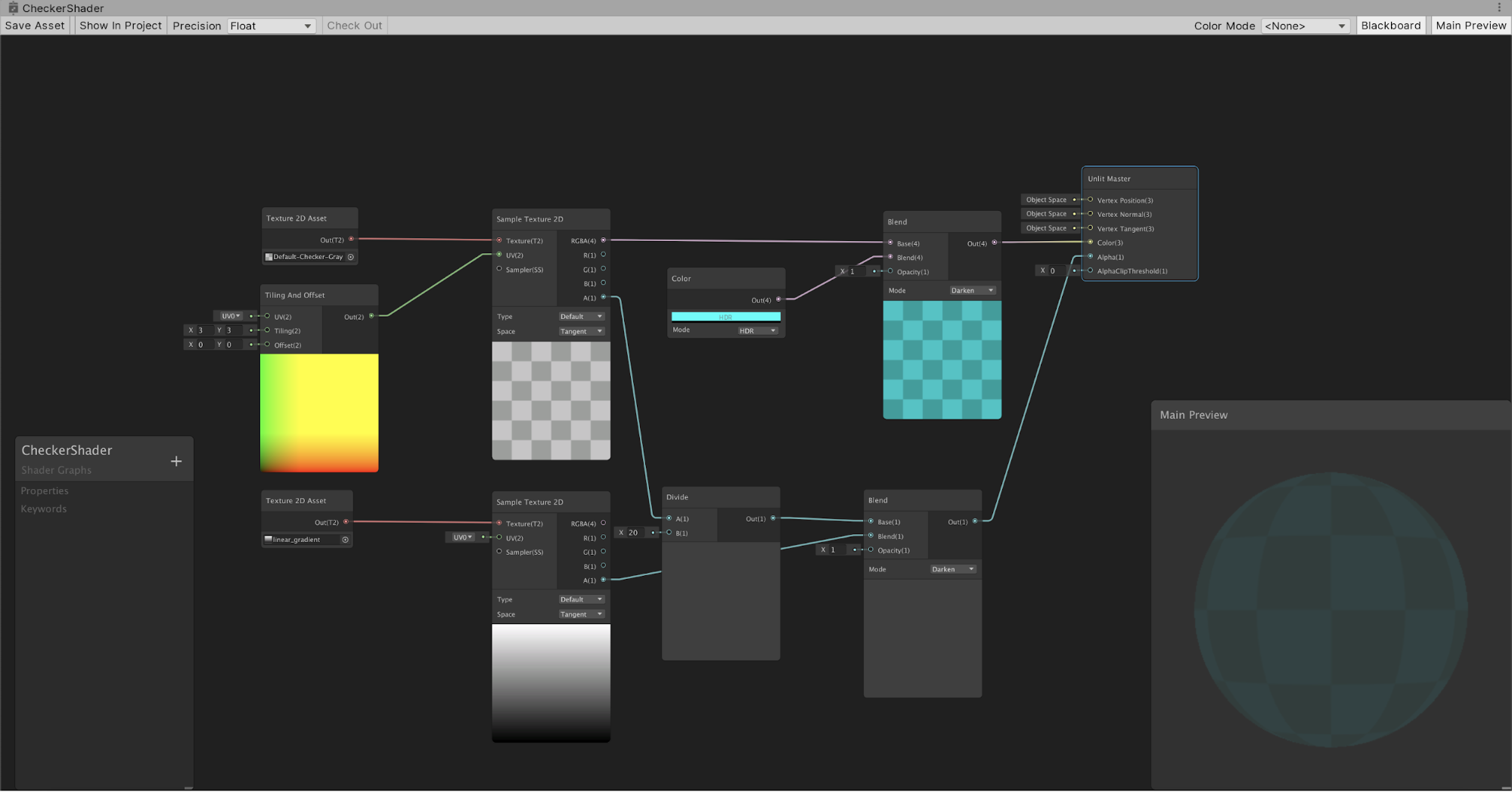
In previous versions of Unity, the only way to create specialized Materials was to program a custom shader or use an outside plugin. With the release of 2018, Unity now has its own native Shader Graph, which can be used to build visually complex Materials using nodes.
Unlike the process of writing code, saving, compiling, and testing in the Editor, the Shader Graph shows you what’s happening to the Material in real-time, allowing you to make changes and experiment on the fly.
Languages available:
1. Creating the Graph and First Nodes
If you are using Unity 2018.1, click here.
1. In the Project window, create a new folder named “Shader Graph”.
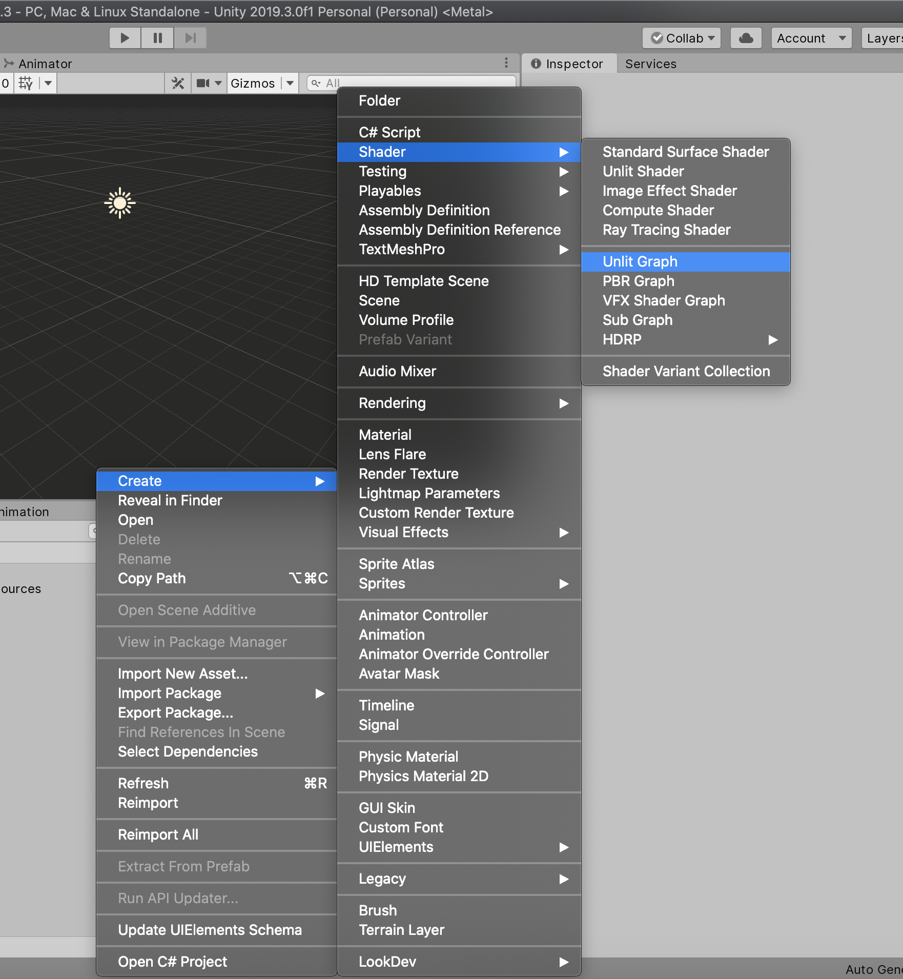
2. Right-click in the Project window and from the Create flyout, navigate to Shader and select Unlit Graph. A new Shader Graph will be generated in the Project window
(Figure 01).
3. Name the new Shader Graph “CheckerShader”.
4. Double-click on CheckerShader to open the Shader Graph window.
5. Dock the Shader Graph window behind the Project window.
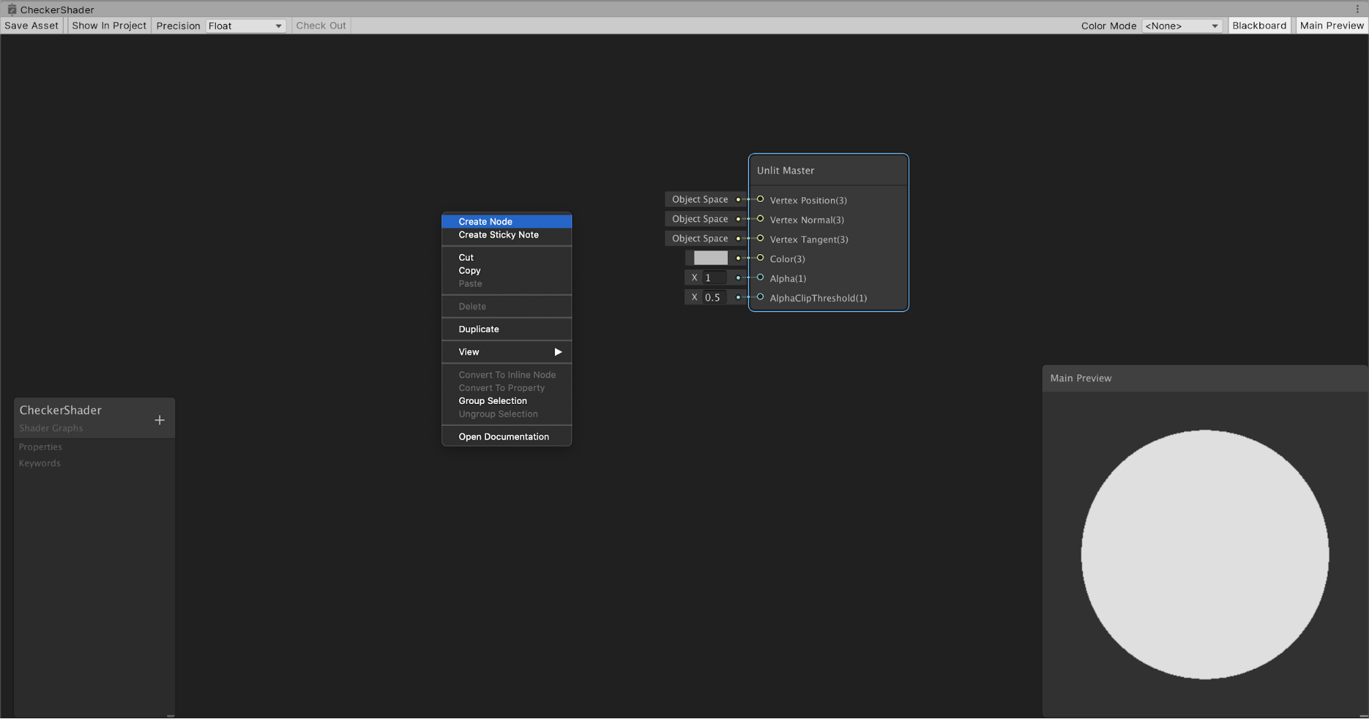
6. Right-click or press the spacebar in the work area, and select Create Node (Figure 02).
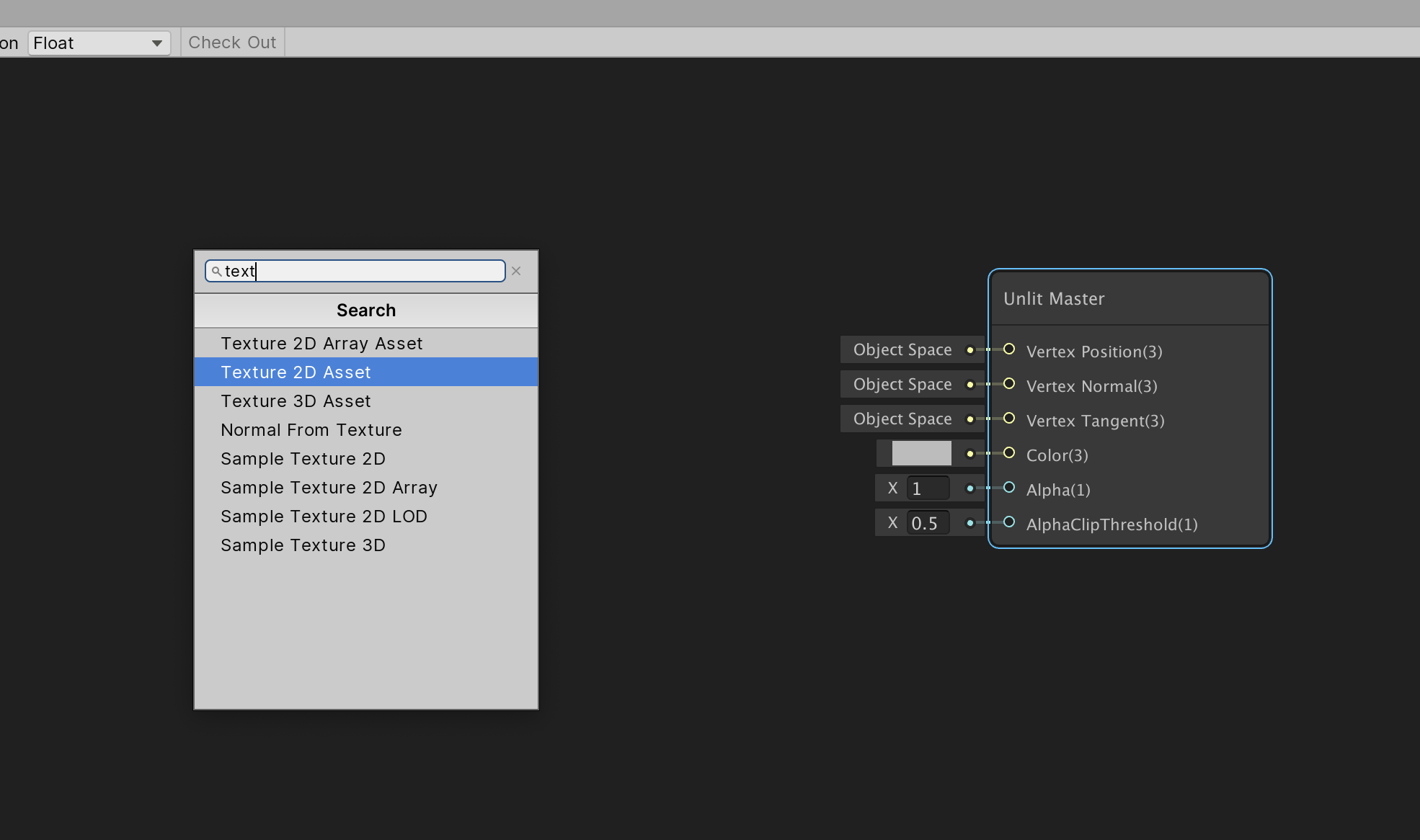
7. At the top of the Create Node window, search for 2D and select Texture 2D Asset (Figure 03).
8. Repeat this process for Sample Texture 2D (Figure 04).
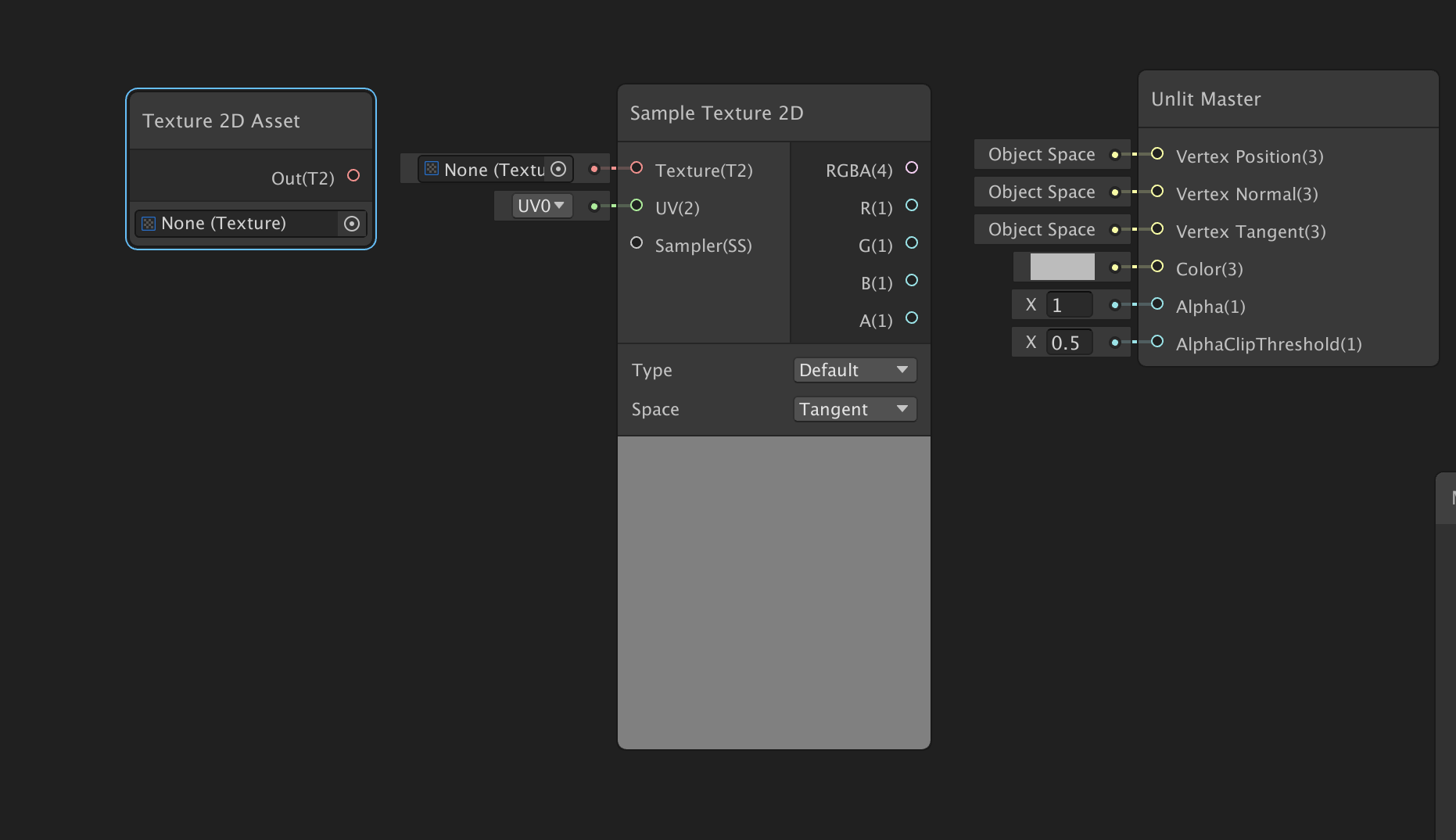
9. In the texture slot at the bottom of the Texture2D Asset, click the Radio button and search for the desired texture.
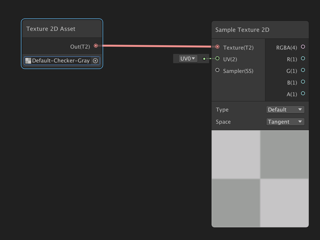
10. Left-click and drag the Out(T) circle in the middle of the Texture2D Asset to pull out a connector line.
11. Drag the connector to the Sample Texture 2D Texture(T) input (Figure 05).
2. Building on the Graph
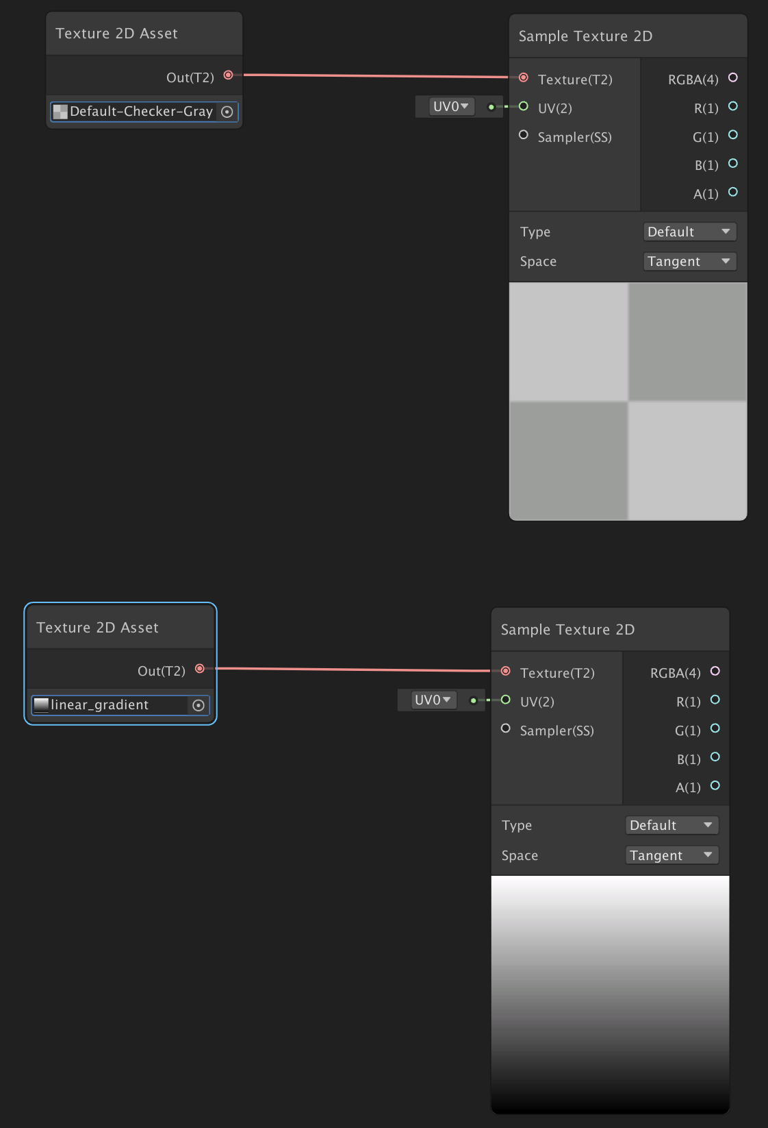
1. Left-click and drag in the work area across the two nodes to select them both.
2. Press CTRL + D (Windows) or Command + D (MacOS) to duplicate them. Move them below the other two nodes.
3. In the second Texture2D Asset Node, search for and apply a secondary texture to blend with, like a Gradient texture (Figure 06).
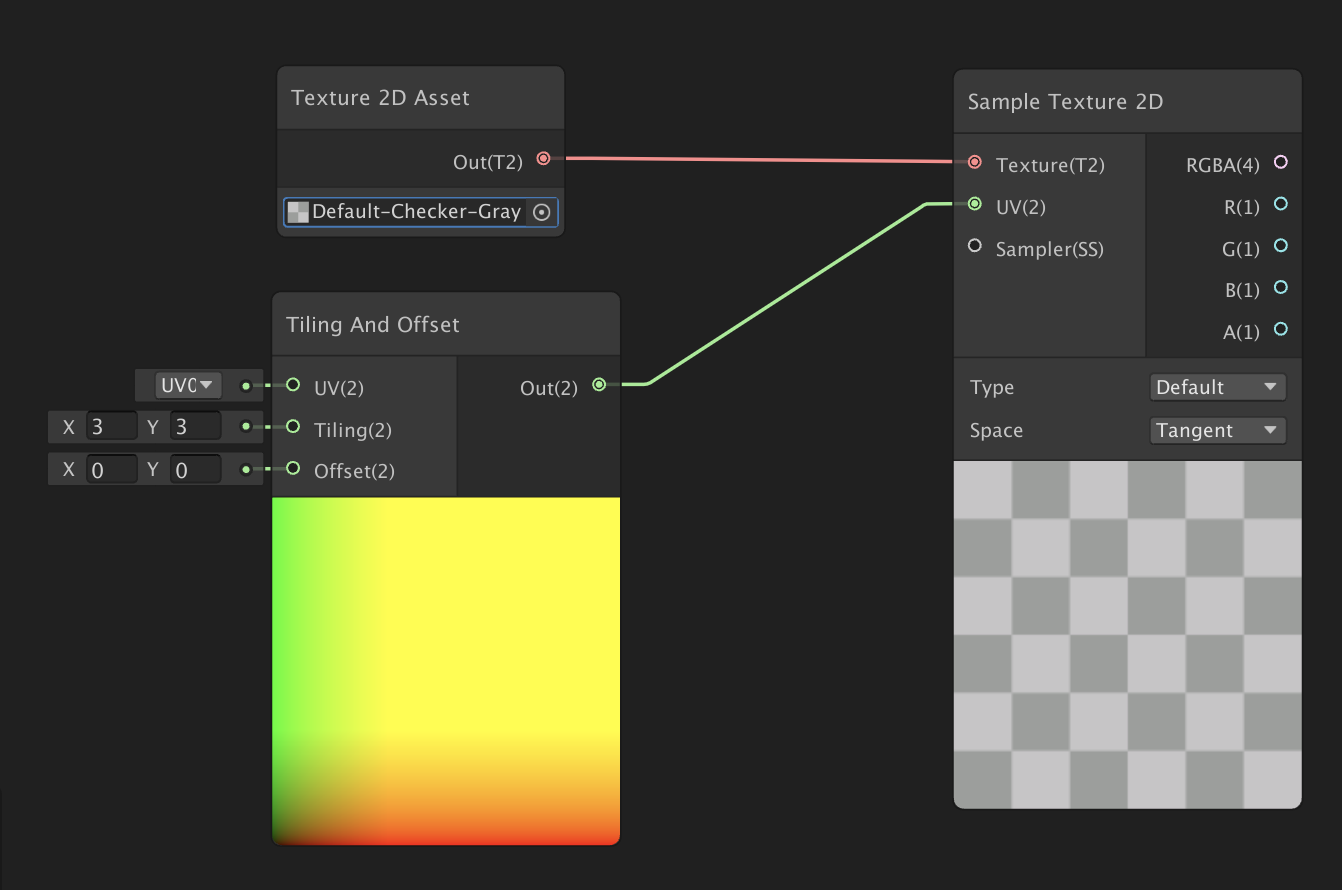
5. Create a new Node, this time selecting Tiling and Offset.
6. Drag the Tiling and Offset Out(2) node to the Checker Sample 2D node.
7. Set the Tiling and Offset Tiling(2) input node to 3 in X and Y (Figure 07).
3. Blending Textures Together
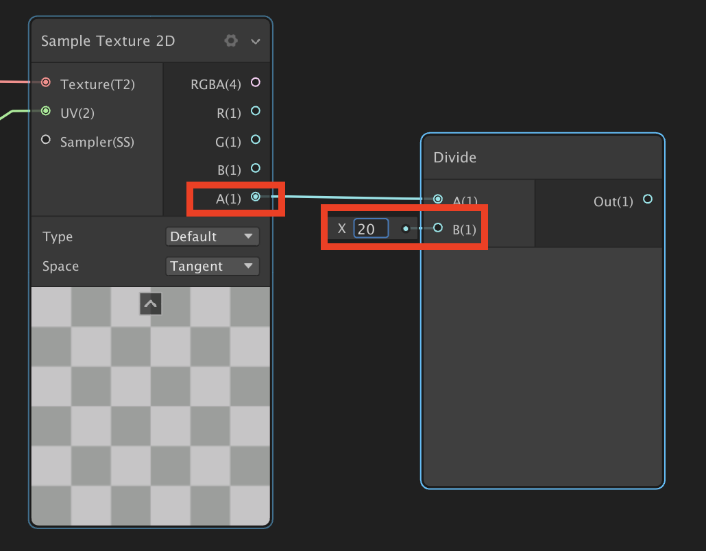
1. Create a Divide node.
2. Drag the A(1) output of the Checker Sample 2D Node to the A(1) Divide Node input.
3. Set the Divide Node’s B(1) X input to 20 (Figure 08).
4. Create a Blend Node.
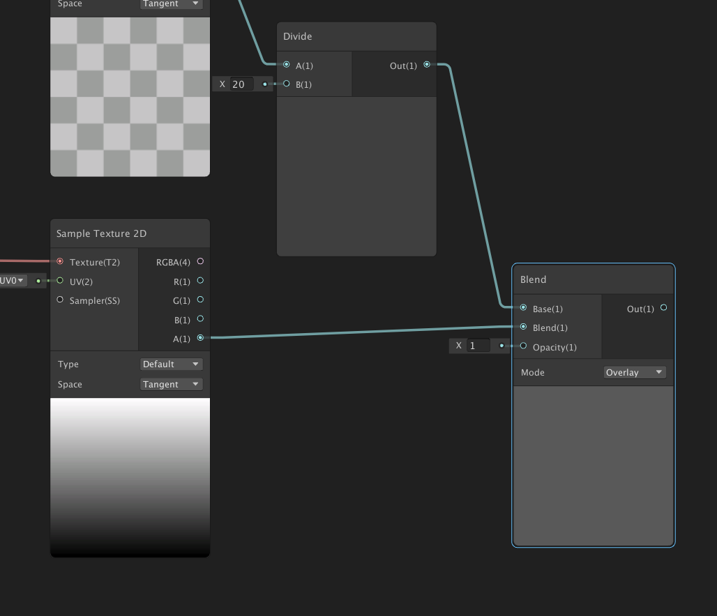
5. Connect the Divide Out(1) output to the first Blend Base(1) input.
6. Connect the Gradient Sample Texture2D A(1) output to the second Blend Base(1) input (Figure 09).
4. Adding Color and Connecting the Shader
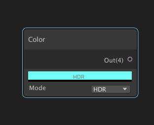
1. Create a Color Node.
2. Set the Color Node to a bright cyan and the mode to HDR.
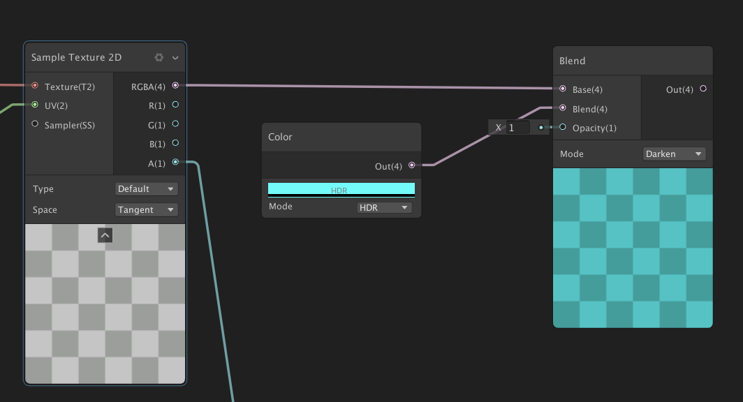
3. Create another Blend Node.
4. Connect the RGBA(4) output of the first Sample Texture2D Node to the first Base(4) Node of the new Blend.
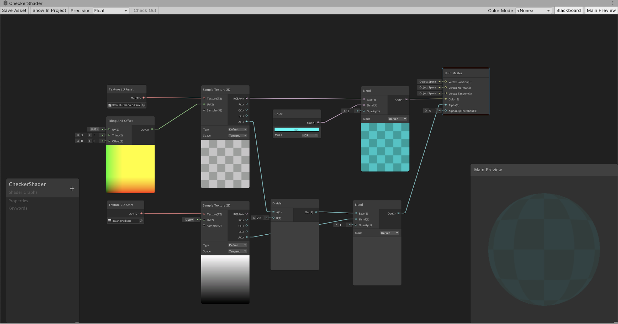
5. Connect the Color Nodes Out(4) output to the Blends second Base(4) (Figure 10).
6. Set the Blend Nodes Mode to Darken (Figure 11).
7. Drag the Blue Blend Nodes Out(4) output to the Unlit Masters Color(3) input.
8. Drag the Gradient Blend Nodes Out(4) output to the Unlit Masters Alpha(1) input.
9. Hit the Cog in the top right of the Unlit Master node and set the Surface to Transparent.
10. In the upper-left corner of the Shader Graph window, click Save Asset (Figure 12).
5. Conclusion
Shader Graphs are incredibly powerful and can become highly complex. There are numerous Nodes to choose from. Now that you know the basics of how to create Shader Graphs, experiment by creating your own.