
Introduction to the VFX Graph - 2019.3
Tutorial
intermediate
+10XP
15 mins
(196)
Unity Technologies
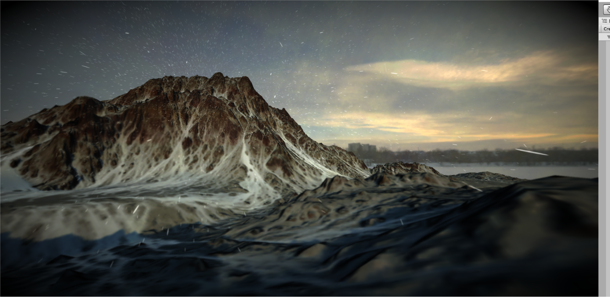
In this tutorial, you will learn the fundamentals of creating particle-driven effects in VFX Graph and later move on to creating effects such as the snowstorm below.
Languages available:
1. Introduction
If you are using Unity 2018.4, click here.
Introduced in Unity 2018.3, the Visual Effect Graph (VFX Graph) is a node-based editor for creating stunning visual effects in real-time. Harnessing the power of the graphical processing unit (GPU) and compute Shaders, VFX Graph can author effects consisting of several million particles simultaneously. This power is also its greatest caveat — particle systems created with the VFX Graph are not affected by physics within your Scene, as they are calculated on the GPU, while physics in Unity are calculated on the Central Processing Unit (CPU).
In this tutorial, you will learn the fundamentals of creating particle-driven effects in VFX Graph and later move on to creating effects such as the snowstorm below.
2. Project Setup
The VFX Graph is packaged with the High Definition Render Pipeline (HDRP) introduced in Unity version 2018.3. Therefore, we must ensure that our project is set up for HDRP before proceeding.
1. Navigate to Window > Package Manager and search for High Definition RP.
2. In the lower-right corner, install the latest version of the pipeline (Figure 01).
From here, let’s create a new visual effect.
3. Right-click under your Assets folder and navigate to Create > Visual Effects > Visual Effect Graph. Name it Snow, or something similar. Create a new GameObject, and navigate to its Inspector view. From there, drag the graph you created to the Inspector. Alternatively, you can drag the graph to the Hierarchy and a GameObject containing the effect will automatically be created in your Scene. Now you can see your effect play back in your Scene. Double-click the graph to open it in the VFX Graph editor (Figure 02).
3. Variables, nodes, blocks, and contexts
At first glance, the VFX Graph appears very similar to the Shader Graph. If you’re familiar with Shader Graph, some of the concepts in the VFX Graph may also be familiar. Before we begin creating an effect, let’s explore the basic components of a VFX Graph: variables, nodes, blocks, and contexts.
Contexts represent the order of operation in which particles are processed and share a similar structure to a C# MonoBehaviour Script:
- Spawn (similar to the Awake() call)
- Initialize (the Start() call)
- Update (the Update() call)
- Output (defines how the resulting particle should be rendered to the screen)
Blocks are operations added to each context (similar to calling functions within the Start() or Update() call). They can be added by pressing the space bar within a context, or right-clicking within a context and selecting Create Block.
In the example above, particles are initialized with both a random velocity and a random lifetime.
The diagram below (provided by John O'Reilly) explains the purpose of each context (Figure 03).
Variables exist on the Blackboard and are used to drive the properties of various blocks and nodes (Figure 04).
To create a new variable, click the + symbol in the top right corner of the Blackboard and select the variable’s data type. From there, simply drag the variable next to the property you want to drive and drag the variable’s output to the property’s input (Figure 05).
When a variable’s Exposed property is checked, it can be modified via the Inspector outside of the VFX Graph editor.
Nodes perform individual operations and are linked together to perform large calculations, much like how they are used in Shader Graph. They can be used in place of variables to drive the properties of Blocks (Figure 06).
4. Conclusion
With this introduction to the fundamental concepts of the VFX Graph, you can now use the power of the GPU to simulate millions of particles in real time.