
Shader Graph: Vertex Displacement
Tutorial
Beginner
+10XP
25m
(464)
Unity Technologies
In this tutorial, we’ll create a Shader Graph to displace the vertices of a mesh along their normals by an amount controlled with procedural noise.
Languages available:
1. Introduction
This tutorial was verified using Unity 2019.4.9f1 LTS and Shader Graph 7.3.1.
Unity’s Shader Graph system allows users to interactively build a Shader as a network of connected nodes. These nodes can represent data about the object to which the Material is applied, mathematical functions, procedural patterns, and more. In addition, the Shader Graph system is extensible, allowing programmers to develop custom Shader Graph nodes.
The Shader Graph system is currently compatible only with projects using the Universal or High Definition Render Pipelines. It’s included in both pipelines’ template projects. If you’re upgrading an existing project to use the HDRP or URP, use the Package Manager to install Shader Graph. Shader Graph can also be updated via Package Manager.
In this tutorial, we’ll create a Shader Graph to displace the vertices of a Mesh along their normals by an amount controlled with procedural noise.
2. Creating and Applying a Shader Graph
1. Create or load a project that uses the HDRP or URP. For this tutorial, we’re using the URP.
2. In the Project panel, right-click and select Create > Shader > PBR Graph (Figure 01). Name it VertexDisplacementSG.
3. Right-click again in the Project panel and select Create > Material. Name it VertexDisplacementMaterial.
4. Click to select VertexDisplacementMaterial and, using the Shader drop-down at the top of the Inspector, select Shader Graphs/VertexDisplacementSG (Figure 02).
5. Using the GameObject drop-down, select 3D Object > Sphere. Assign the VertexDisplacement Material to the new Sphere.
3. Building a Shader Graph
Our Shader Graph will move a vertex along its normal. The amount by which it’s moved will be determined using a procedural noise function. The position of the vertex before displacement will be used in the calculation of the noise. As we will see a bit later, the space in which we consider the vertex position affects the behavior of the noise, and thus the displacement.
1. In the Project panel, double-click VertexDisplacementSG to open the Shader Graph Editor window.
2. Right-click in the Shader Graph Editor and select Create Node. Select Input > Geometry > Position.
3. Click the Space drop-down and select Object (Figure 03).
4. Create another node. Select Procedural > Noise > Voronoi.
5. On the right side of the Position Node, click and drag from the socket labeled Out(3)., Release the mouse over the socket labeled UV(2) on the left side of the Voronoi node (Figure 04). This will cause the Voronoi noise node to use the position of the vertex when calculating the noise pattern.
6. Create another node by selecting Input > Geometry > Normal Vector. Set Space to Object.
7. Create another node by selecting Math > Basic > Multiply.
8. Connect the Out socket of the Normal Vector and the Voronoi noise nodes to sockets A and B of the Multiply Node (Figure 05).
9. Create another Node by selecting Math > Basic > Add.
10. Connect the outputs of the Position and Multiply nodes to input sockets A and B of the Add node.
11. Connect the output of the Add node to the Vertex Position input socket of the PBR Master node.
12. Our Shader Graph is complete. Click Save Asset in the upper left corner of the Shader Graph Editor and close the window (Figure 06).
4. Object vs. World Space
1. In the Scene view, select your Sphere and move it around. Notice that the displacement pattern is consistent—the peaks and valleys don’t change based on where the Sphere is in the Scene (Figures 07 & 08).
2. Open VectorDisplacementSG for editing by either double-clicking it in the Project view, or single-clicking and selecting Open in the Inspector.
3. In the Position node, set Space to Absolute World.
4. Save the Shader Graph and return to Scene view.
5. Try selecting and moving the Sphere again. Notice that the noise pattern and displacement amount depend on the world position of the vertex. The Sphere seems to be swimming through it, though there’s an unintended effect with using World Space for the Position Input. With this configuration, the world position is added to itself, doubling its distance from the World Origin.
6. Open VertexDisplacementSG for editing.
7. Right-click the connection between the Position and Voronoi nodes and select Delete.
8. Create a new node by selecting Input > Geometry > Position. Set its Space to World, and connect it to the UV input of the Voronoi node. This will cause the Voronoi noise to be calculated based on the vertex’s position in the world.
9. Set the Space of the original Position node to Object (Figure 09). Save changes and close the window.
10. Once again, select and move the Sphere. Notice that the displacement pattern still stays with the world, giving the effect of a cloud changing shape as it moves through the sky, but the Sphere never moves away from the Transform gizmo.
5. Adjusting Shader Graph Strength
Finally, suppose that we want to control the strength of this effect. For this exercise, we’ll create a slider directly in the Shader Graph. In production, this slider would be replaced with a property that’s accessible via code. This adjustability allows for effects such as modulating the displacement amount by the volume of a music track for an audio visualizer.
1. Open VertexDisplacementSG in the Shader Graph Editor.
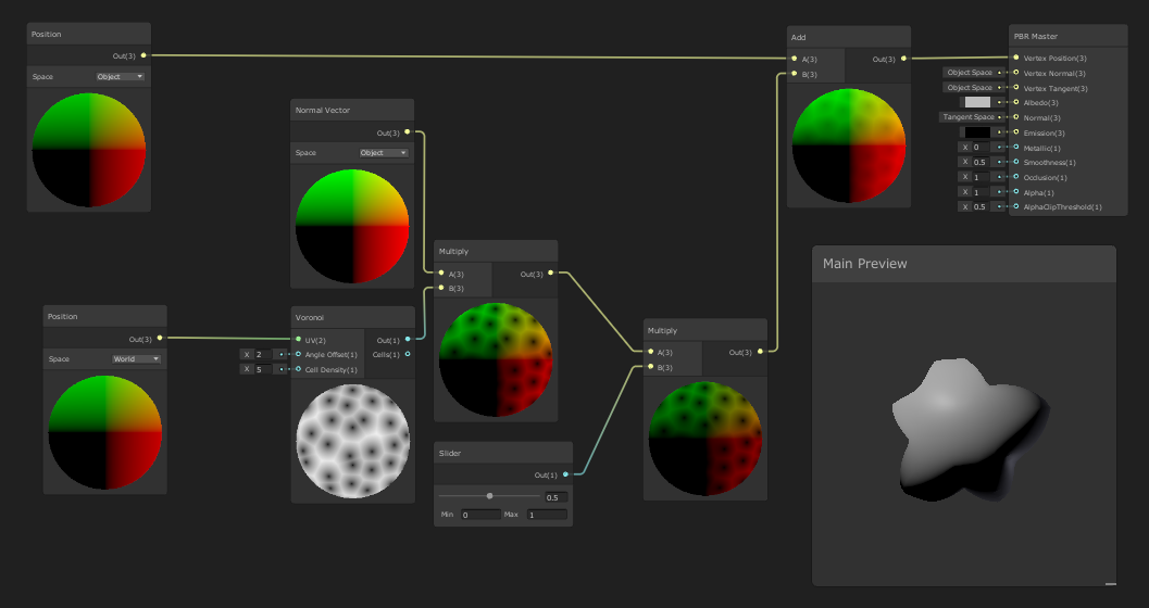
2. Create a new node by selecting Input > Basic > Slider.
3. Create another by selecting Math > Basic > Multiply.
4. To the inputs of the new Multiply node, connect the outputs of the Slider and the original Multiply node.
5. Connect the new Multiply node to an input of the Add node, replacing the original Multiply node (Figure 10).
6. Save any changes and close the window.
6. Conclusion
This tutorial has just touched upon the power of Mesh manipulation using the Shader Graph system. Experimentation with the different nodes and settings will uncover a plethora of potential applications.