
Tessellating meshes in PiXYZ Studio
Tutorial
Beginner
+10XP
30 mins
(14)
Unity Technologies
Tessellation is the process of converting a patch-based CAD file to a polygonal mesh. It is the first and most important step in preparing an object for use in realtime graphics. In this tutorial, you will learn how to tessellate a mesh in PiXYZ Studio.
Languages available:
1. Introduction
This tutorial has been verified using Unity 2019 LTS and PiXYZ 2020.1.1.8
Tessellation is the process of converting a patch-based CAD file to a polygonal mesh. It’s the first and most important step in preparing an object for use in real-time graphics.
2. Preparing Your Mesh for Tessellation
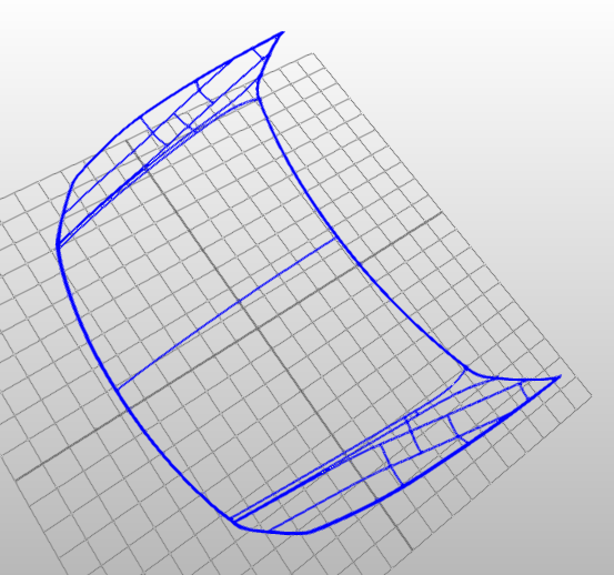
Before you tessellate your mesh, it’s important to make sure there are no breaks in surfaces where they should be closed/continuous. To view the surface edges of your mesh, enable Wireframe visibility in the upper right corner. (Figure 01)
PiXYZ Studio represents surface edges as solid blue outlines. On a patch-based model, these should only be at the boundary edges of the mesh. Errant boundaries on surfaces (Figure 02) will cause cracks in the generated polygon mesh.
To repair a CAD mesh, select Repair CAD from the CAD dropdown. (Figure 03)
For more information about Repair CAD and repairing open surfaces, see Cleaning Open Meshes in PiXYZ Studio tutorial. A correctly constructed CAD mesh will have lines only at the boundaries of the mesh. (Figure 04)
To tessellate a mesh, select the mesh (either in the 3D view or the Product Structure), and from the CAD dropdown, select Tessellate. (Figure 05)
An options window will appear. (Figure 06)
Options are:
Preset: Allows you to create, save, or delete presets to set all options at once
Max Sag: This is the maximum distance between the CAD mesh and the resulting polygonal mesh. The lower this value, the higher the quality of the resulting mesh.
Max Length: This is the maximum length of the elements. It isn’t recommended for rendering in most situations, but can help avoid issues for meshes with extremely long parts, such as airplane wings.
Max Angle: This is the maximum angle between the normals of any two adjacent elements. This helps retain fidelity in situations such as small radius fillets.
Advanced options (Figure 07) are:
Create Normals: PiXYZ Studio can generate normals for the tessellated mesh.
UV Mode:
- No UV: No UVs will be generated.
- Fast UV: Lower-quality UVs will be generated, but faster.
- Uniform UV: More uniform UVs will be generated.
UV Channel: If generated, the channel of the UVs.
UV Padding: This is the amount of space [0-1] between UV patches. PiXYZ Studio will attempt to respect this, but may not always be able to.
Create Tangents - If enabled, tangents will be generated for the tessellated mesh.
Create Free Edges: If enabled, free edges will be created for patch borders.
Keep B Rep Shape: If enabled BRep shapes will be kept for Back to BRep or Retessellate
Override Existing Tessellation: If enabled any already tessellated parts will be retessellated
Choose your options and click Execute. (Figure 08)
3. Checking the Quality of the Tessellation
An easy way to check the quality of the tessellation is to check its specular highlights. To do this, click the Checker button and select Specular from the dropdown. (Figure 09)
Selected surfaces are still yellow, but all forward-facing surfaces are now orange. (Figure 10)
4. Repairing the Tessellated Mesh
If you need to repair a mesh after tessellation, click to select the offending occurrence and select Repair Mesh from the Mesh dropdown (Figure 11). This will merge vertices that are less than the given distance apart. It will optionally also create cracks at non-manifold edges and attempt to orient the faces. It’s important to note that, as with Repair CAD, Repair Mesh can potentially remove small details on a mesh.
5. Conclusion
Tessellating your mesh is the first step toward making it usable in real-time graphics. Proper preparation and tessellation will optimize the amount of cleanup.