
Working with Hexagonal and Isometric Tilemaps - 2019.3
Tutorial
Beginner
+10XP
30m
(192)
Unity Technologies
In addition to Square and Rectangular Tilemaps, Unity can also create Hexagonal and Isometric Tilemaps.
Languages available:
1. Creating a Non-Rectangular Tilemap
If you are using Unity 2019.2 or below, click here.
Creating a Hexagonal or Isometric Tilemap is almost identical to creating a traditional Tilemap.
Right-click in a blank area of the Hierarchy panel, or use the top dropdown menu: GameObject > 2D Object > Hexagonal / Isometric Tilemap (Figure 01).
The four types of Tilemaps are pictured below (Figures 02 - 05).
Note that when referring to a Tilemap Grid’s X, Y, and Z axes, the Tilemap Grid’s Cells, (sometimes referred to as a “swizzle”), indicates that the direction of the perspective axes are swapped when displaying onto the Tilemap. For example, a Tilemap with an YXZ Grid transposes X with Y as a means to re-order elements on a side-scroller 2D scene. For example, if your character walks sideways (along the X-axis) and jumps (along the Z-axis), your background consists of tiles that you may want to target to a specific position. Tilemaps, however, work with the X and Y axes, not the X and Z axes. You are then able to swap, or Swizzle your character position's Y and Z coordinates.
2. Working with Hexagonal Tilemaps
By default, a Tilemap Grid’s cell size is set to 1 x 1 units, which is fine for a traditional Tilemap Grid with square tiles, where a cell’s pixels-per-unit matches its resolution. For Hexagonal and Isometric Tilemaps, we will need to change the pixel-per-unit resolution. To find our cell size, we will divide the cell’s pixel resolution by its pixels-per-unit setting.
We will assume that the tile Sprites (Figures 06 - 08), have been imported with the default resolution of 100 pixels-per-unit, with their pivot points set to center.
Hexagonal Point Top Tilemap: Our tile for the Hexagonal Point Top Tilemap is 55 x 64 pixels. With a pixels-per-unit setting of 100, our cell size is .55 inches for X, and .64 inches for Y (Figure 09).
Hexagonal Flat Top Tilemap: The tile for the Hexagonal Flat Top Tilemap Grid has its initial tile rotated. Its dimensions are 64 x 55 pixels. You might expect the cell size to be .64 inches for X, and .55 inches for Y. However, with this setting, you will get an incorrect fit (Figure 10). This is because the Cell Swizzle for the Hexagonal Flat Top Tilemap Grid is YXZ. In other words, what looks like the X axis from our perspective is actually the Y axis, and vice versa. This means you will need to transpose the X and Y components of the cell size in order for them to be set properly. With the same cell size as in the Hexagonal Point Top Tilemap, .55 inches for X and .64 inches for Y, we get a much better fit (Figure 11).
3. Working with Isometric Tilemaps
While Hexagonal Tilemaps can easily be dragged into place from the Project view, Isometric Tilemaps benefit greatly from the Tile Palette window. In fact, the Tile Palette window is required to use the Z As Y Tilemap feature.
Isometric Tilemaps are 2 x 1 in aspect ratio. Because they can vary in height, and in order to accommodate flat terrain as well as tall trees in the same Tilemap, we only consider the footprint of the tile. The 2 x 1 rule allows for clean tiling and greatly simplifies the math for calculating cell size.
A good practice is to match your pixels-per-unit setting for your Isometric Tilemaps to their width. So, a tile that is 100 pixels wide would be set to 100 pixels-per-unit. This allows your Isometric Tilemap to use the default cell size of 1 x 0.5.
Even though the base of the tile conforms to the 2:1 aspect ratio, the art itself usually doesn’t. The only exception is with flat isometric tiles with no height information. Even the most “flat” art will typically contain some height information. The example ground tile (Figure 12), enlarged for detail, is 100 x 58 pixels tall. This means there are eight pixels of height information. In this instance, it happens that four of the pixels are above ground and four are below (Figure 13).
One final point to consider is the apparent height of your tile. There are two methods to control this: the Pivot-point and the Z Position for Isometric (Z As Y) Tilemaps.
The Pivot-point is better suited to change the apparent depth or height of a tile. Though their cells are at the same vertical position, these trees appear at different depths. The tree on the left is using the default center pivot-point, while the tree on the right’s pivot-point is set at the bottom of its trunk (Figure 14). To create this terrace, the grass-on-ground tile was duplicated, and the duplicate tile’s pivot-point was moved slightly below center, raising its apparent elevation (Figure 15).
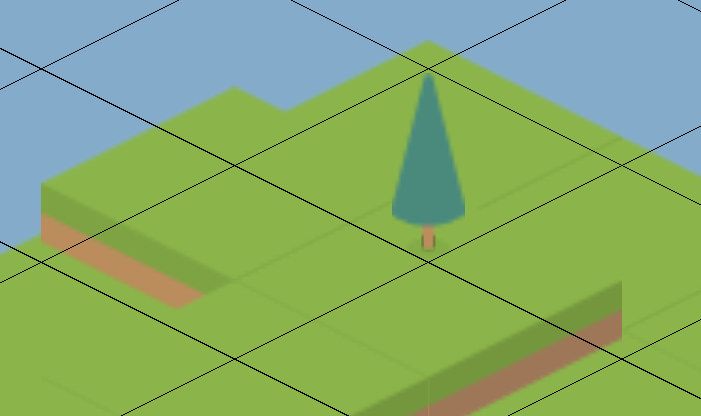
Setting the Z Position in an Isometric (Z As Y) Tilemap offers less control over apparent position, but is a better choice when you need to stack two tiles in the same cell, such as planting a tree on our terrace (Figure 16).
The tree has a Z (effectively Y) Position of 1, while the grass tile’s Z Position is 0. To set the Z Position of a tile, press S in the Tile Palette or use the selection tool (Figure 17), and select the tile you wish to raise or lower.
Changing the Z position will change the offset of the tile between where you select (the lower-orange diamond) and where it appears on the Tilemap (the upper-blue diamond) (Figure 18). Select Reset to bring the tile back to ground level with a Z Position of 0.
4. Conclusion
Now that you know about non-rectangular Tilemap options such as Hexagonal Tilemaps or Isometric Tilemaps, you can experiment with them to give your 2D games and other projects a more interesting layout and navigation scheme.