Working with SpriteShape
Tutorial
Beginner
+10XP
15 mins
89
Unity Technologies
SpriteShape lends an organic, hand-crafted feel to projects by allowing you to tile Sprites along a path, rather than the typical grid pattern.
Languages available:
1. Working with the 2D SpriteShape Package
This tutorial has been verified using Unity 2019.4.14f1 LTS and 2D SpriteShape 3.0.14
The 2D SpriteShape package lends an organic, hand-crafted feel to projects by allowing you to tile Sprites along a path, rather than the typical grid pattern. The path can be open-ended or closed. Open-ended SpriteShapes are great for platforms, ladders, or level decor. Closed SpriteShapes are useful for solid areas of the level. The SpriteShape system is used via two components, both explained in greater detail later in this workflow: the 2D SpriteShape Profile and the 2D SpriteShape Controller.
2. Installing the 2D SpriteShape Package
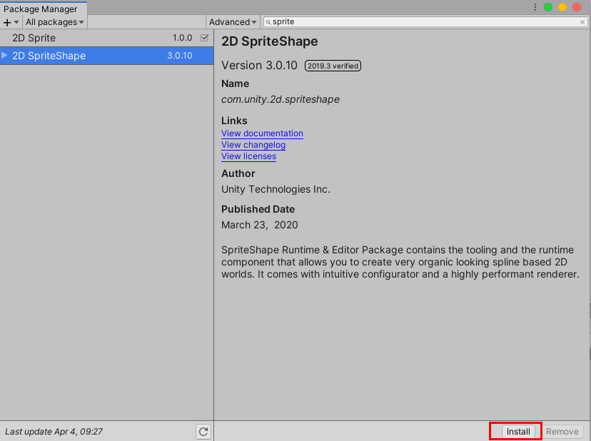
The 2D SpriteShape package is available to download from the Package Manager. To install it, From the dropdown menu, select: Window > Package Manager, and from the Packages list on the left hand column, search for and select: 2D SpriteShape, and select the Install Button (Figure 01).
3. The SpriteShape Profile
The SpriteShape Profile is how you specify which Sprites should be shown when the SpriteShape path is at certain angles.
To create a SpriteShape Profile, from the Assets dropdown, or by Right-clicking a blank area in the Project panel, select Create > SpriteShape Profile > Open Shape, or Closed Shape.
The Open Shape profile is used to create Shapes made from a single edge outline with tiled Sprites along its edge. This profile is ideal for creating level elements such as platforms. The Closed Shape profile is used to create Shapes that encompass an enclosed area. The Closed Sprite Shape can display and tile a Fill texture in the enclosed area, if a Fill texture is set in its Profile settings. Use this preset to create large solid filled Shapes that are ideal for backgrounds or large platforms.
In this tutorial, we will create an Open Shape SpriteShape Profile, and explore its Inspector Window values, section-by-section, beginning with Control Points (Figure 02).
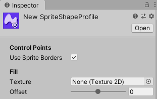
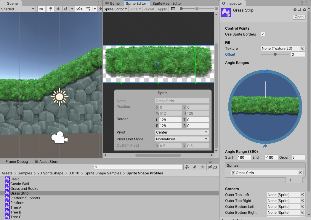
Use Sprite Borders: Enable the checkbox to draw Sprite Borders on any discontinuities. You can define the Sprite Borders in the Sprite Editor Window, (from the menu dropdown, select: Window > 2D > Sprite Editor.
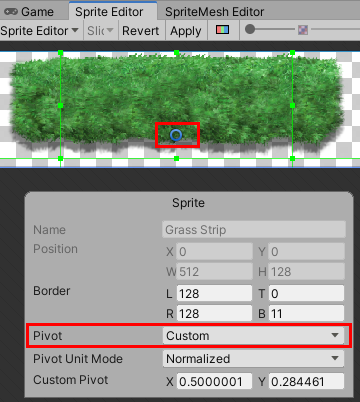
Here in this tutorial, we will use the ‘Grass Strip’ Sprite example provided with the 2D SpriteShape Package. Drawing Sprite Borders on a Sprite is similar to utilizing the left and right tile in a 3-piece Rule Tile, commonly used for platforms (Figure 03).
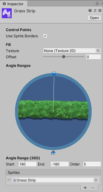
Fill: The Fill settings are applied across all Angle Ranges in the SpriteShape Profile (Figure 04).
Texture: The image to use for the fill. The fill texture must be its own image, rather than on a Sprite Atlas, with its wrap mode set to Repeat.
Offset: This controls how far in or out from the curve the fill area extends. A setting of 0 has no effect, while negative values will cause the fill to recede into the shape. Positive values will cause the fill to reach beyond the SpriteShape Path. The Fill is layered behind the SpritePath.
Angle Range (360): The Angle Range determines which Sprite is displayed when the SpriteShape path bends at certain angles (Figure 05).
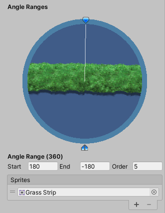
Each Angle Range consists of a start and end angle and a list of Sprites to be shown when the SpritePath’s angle is within that range.
To add multiple Sprites at once, select them in the Project View and drop them on the word “Sprites” at the top of the list, or select the + button to add the Sprites individually. The Sprite will attach to the SpriteShape spline at its pivot. If you’re making a row of trees and plants, set their pivots to Bottom in the Sprite Editor Window (Figure 06). For stalactites or hanging gardens, etc., set the Pivot point to the Top.
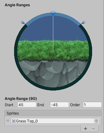
By default, only the first Sprite in the list is shown. This can be changed per SpriteShape path segment, using the SpritePath Controller, which is covered later in this workflow. Note that, unlike the Unit Circle, 0° is at the top of the circle. The angle increases in a counterclockwise fashion, and decreases clockwise, from 0°.
The blue pointer at the top of the circle is the Preview Handle, and can be dragged around the circle to check which Sprite is shown at any angle. The Preview Handle is always opposite the Angle Range whose sprite is shown in the center. When the Preview Handle is at the top of the circle, as in our example, it’s pointing down at the ground rocks, so the ground Sprite is shown (FIgure 07).
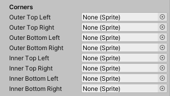
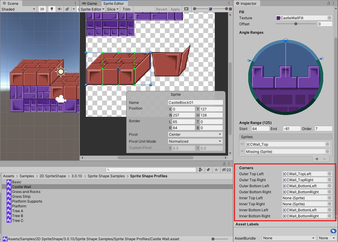
The final section of the SpriteShape Profile Inspector is Corners.
As with Fill, the specified Sprites are used across all Angle Ranges in the SpriteShape Profile. Where a 9-Sliced Sprite only allows you to set outer corners, a SpriteShape Profile can have separate Sprites for the inner and outer corners (Figure 08).
In another provided asset example: ‘Castle Wall,’ you can see the assigned corners specified in the Castle Wall SpriteShape Profile (Figure 09).
4. The SpriteShape Controller
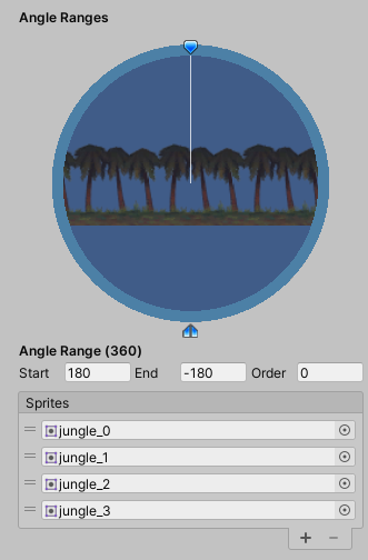
Once you’ve created and configured at least one SpriteShape Profile, you’re ready to create the SpriteShape Controller. For this exercise, we will first create an Open Shape SpriteShape Profile, and add at least two Sprites to the default Angle Range. Here, we’ve added 4 jungle Sprite assets (Figure 10).
To create a SpriteShape Controller, right-click a blank area in the Hierarchy panel and select
2D Object > Sprite Shape. A default Solid white SpriteShape is created, with the name:
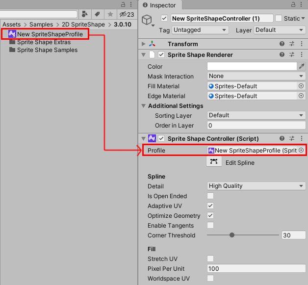
‘New SpriteShapeController’. To get started, drag the Sprite Shape Profile you created earlier from the Assets folder, into the slot labeled Profile, in the Sprite Shape Controller component in the Inspector window (Figure 11).
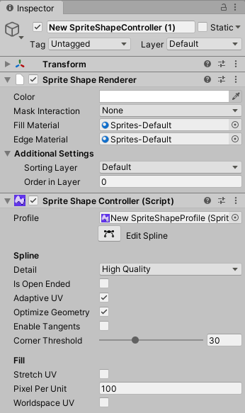
The SpriteShape Controller consists of a SpriteShape Renderer, which functions identically to a Sprite Renderer, and a SpriteShape Controller, which allows you to edit the path of the SpriteShape, and adjust its tangent values (Figure 12).
If you were making a solid piece of terrain, you’d want to leave Is Open Ended unchecked. For now, select to enable a checkmark to the Is Open Ended checkbox, and then select the Edit Spline button. In the Scene view, our shape is now made up of three segments, with each point represented by a white control point (Figure 13). You can add more points to the SpriteShape spline by clicking along the edge between any two existing points.
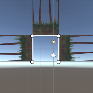
Drag a box around a point and select it. When selected, a point turns yellow and information specific to that point and its segment appear in the Inspector (Figure 14).
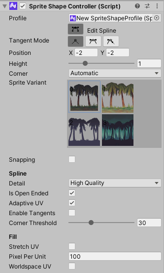
You can now edit settings specific to this point, including the Sprite Variant shown and the Tangent Mode. Tangent Mode controls the behavior of the two tangents associated with the point, which determines the shape and smoothness of the curve. The three settings are:
Linear: Straight lines lead into and away from the point. This is great for hard, craggy surfaces as well as retro-style terrain.
Continuous: The two tangents mirror each other’s angle and length, depending on the distance to the neighboring points. This helps ensure a smooth curve at any angle.
Broken: Tangents are not linked. This is useful for introducing sharp angles or points into the curve. On endpoints, only the inner tangent has any effect, as there is no next point for the outer tangent to lead to.
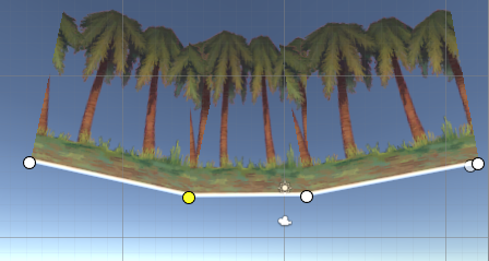
Explore the different Tangent Modes with the different control points, and change or modify some of these points. Here, we’ve layered the jungle trees along a custom slope (Figure 15).
5. Adding a Collider to your Sprite Shape
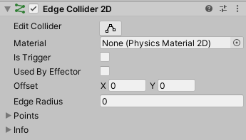
To make your SpriteShape walkable, add an Edge Collider 2D Component to an Open SpriteShape, or a Polygon Collider 2D Component to a Closed SpriteShape (Figure 16).
You can adjust the Collider’s Offset to adjust where ground level is in the SpriteShape by changing the X and Y values. This is especially useful for angled views where the player is vertically centered in the platform.
6. Conclusion
The best way to familiarize yourself with the SpriteShape system is to dive in and start creating. The Open Shape SpriteShape Profile is a great place to start. Utilize the Closed Shape SpriteShape Profile if you’re already familiar with Tilemaps, Rule Tiles, and 9-Sliced Sprites.