Control what your camera sees
Tutorial
Beginner
+10XP
15 mins
131
Unity Technologies

In this tutorial, you’ll learn how to fine tune what appears within the camera view with clipping planes, culling masks, and environment properties.
By the end of this tutorial, you'll be able to:
- Fill in the background of the Main Camera view.
- Control the field of view of the Main Camera by adjusting the frustum.
- Control the depth of view of the Main Camera by configuring the clipping planes.
Languages available:
1. Overview
You now know how to use projection properties to control how a camera renders a scene. With these skills you have some control over what appears inside and outside of a shot, but there are further configurations you can make to fine-tune how objects within a camera’s field of view appear — or don’t appear, as the case may be! In this tutorial, you’ll learn how to use clipping planes, culling masks, and environment properties.
2. Define the limits of the camera view with clipping planes
Clipping planes define the scope of what a camera can see in a scene. There are stylistic reasons to limit the distance a camera can see, but editing clipping planes is primarily used for optimization purposes. The less of a scene a camera has to render, the lighter the processing load for an application.
There are two clipping plane values: near, which defines how close an object is able to get to the camera while still rendering, and far, which defines how far away an object can be before it’s no longer visible on screen. A white wireframe in the Scene view shows you the locations of these planes. For perspective cameras, the wireframe is a pyramid shape, and for orthographic cameras, the wireframe is a rectangle.
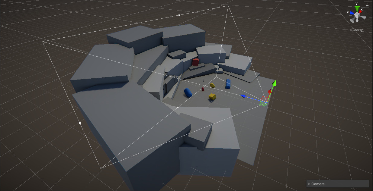
Let’s set the clipping planes on our camera:
1. In the Scenes folder, locate and open Camera_Limits_Scene.
2. Switch to the Game view so you can see through the Main Camera at a larger scale.
3. With the Main Camera selected, click the Far clipping plane parameter in the Inspector to make it active.
4. Change the Far clipping plane value from 1000 to 10, then change it from 10 to 1.
Notice that as Far value is reduced, the amount of content visible in the background decreases. In place of the objects that were previously visible, the empty area is filled with the background – in this case, the default skybox. By all appearances, the previously existing background objects simply cease to exist in the scene.
5. In the Game view and with the Main Camera selected, left-click and drag on the Z position value to pan your camera forward.
6. Continue panning forward until the background objects come back into view.
As you pan through the scene, objects that appeared to be absent from the scene will suddenly appear in view as they enter the camera’s far clipping plane, as if they’re materializing from the skybox itself. While this effect can be stylistically interesting, under most circumstances viewers would find this visually jarring and difficult to navigate. Unless this effect is part of a specific design, it’s best practice to keep the far clipping plane at a high value so that the user doesn’t notice when objects start to render on the screen. The default value of 1000 is usually right. Restore this value now.
7. The near clipping plane works on a similar principle. In the Scene view, move the camera in close to the character until part of the character appears to be cut off.
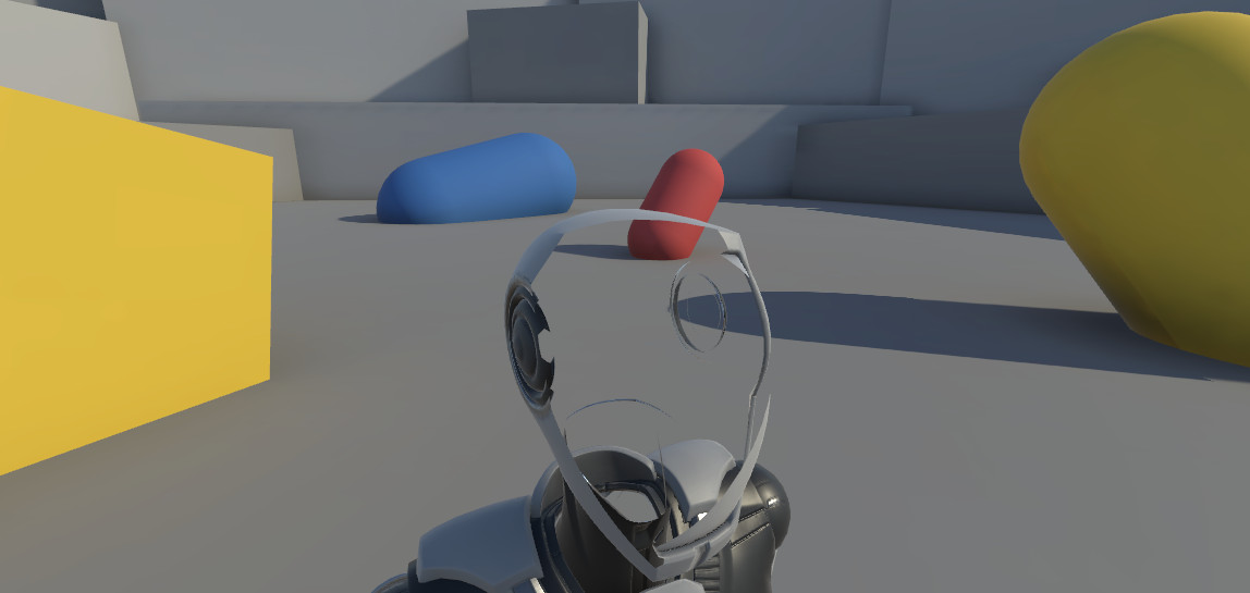
If you play a lot of video games, this may be a familiar sight. When objects get too close to the camera, parts of them move outside of the near clipping plane, giving the user a view of the interior of the mesh. Because objects in this scenario tend to take up a large amount of the screen, this can be just as distracting as objects that suddenly fade into view at the far clipping plane. Generally speaking, you should avoid this issue by adjusting the character controller so objects never get this close, but if that isn’t practical, you can reduce the value of the near clipping plane.
3. Use culling masks to show or hide objects
You now know how to adjust the minimum and maximum ranges a camera will render using clipping planes, but what about objects that exist within those two values? There are many situations where you might want to control the visibility of objects in a scene without adjusting the objects themselves. For example, you might have multiple types of specialized cameras available for the user to toggle on and off in a search and rescue simulation; the user might be able to toggle a thermal imaging camera on, which would allow them to see objects that would otherwise be invisible. You can hide and reveal objects with the camera through the use of culling masks.
1. In the Scene view, select the red capsule and press F on your keyboard to focus on it.
2. In the Inspector, select Layer > Add Layer.
3. In User Layer 6, enter “Culled”.
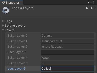
If you’ve ever created scripts in Unity, you might have used tags to reference objects that exist in the scene where the script is used. Layers serve a similar purpose to tags in Unity, in that they allow you to add an identifier to an object or set of objects. You can then use these identifiers to perform specific actions on anything that they’re assigned to. Whereas tags are designed only to be used through scripts, the Layer system is built into many default components within the Editor, including the camera.
4. Reselect the red capsule in the scene.
5. Assign the Culled layer to the red capsule by selecting it from the Layers list in the Inspector.
6. Select the Main Camera.
7. In the Inspector, locate the Culling Mask option in the Rendering section of the Camera component, and disable Culled.
In the Scene view, nothing appears to have changed, but looking through the Main Camera view will reveal that the object placed on the Culled layer no longer appears in the scene! Because the object in the scene is actually still present, the user will be able to continue to interact with it in the same way — it’s simply invisible to the camera.
4. Change the background type
As described in Creative Core: Lighting, by default all new scenes come with a procedural skybox. This skybox is tied to the directional light, which is also provided by default. Together these two objects contribute to the ambient light of the scene. While the skybox and lighting are determined by the skybox shader and lighting properties, it is the camera that manages whether or not the skybox is visible in the scene.
Let’s take a look:
1. Adjust the camera so you can see the skybox in the scene.
2. In the Inspector, locate the Environment section of the Camera component.
3. Select the Background Type option and change it from Skybox to Solid Color.
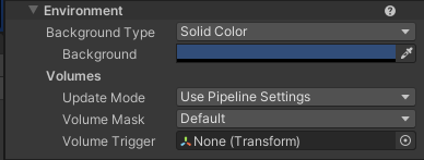
If you look at the camera preview window or switch over to the Game view, you’ll see that the skybox has been replaced with a flat blue color. This is only occurring within the camera view — the skybox is still present in the scene. The environment parameters are defined per camera, so if multiple cameras were present in the scene, one could still be set to render the skybox.
4. Click the color swatch for the new Background value and change it to a bright green.
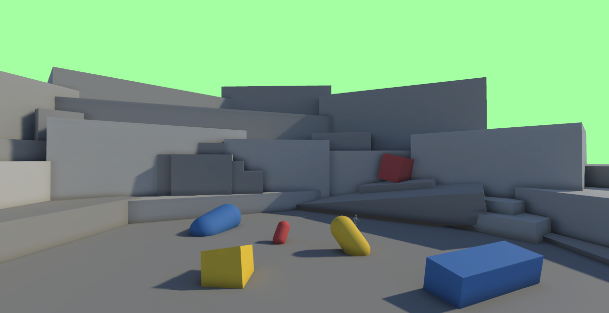
It’s important to note that the Solid Color setting for Background Type in no way affects the lighting in the scene, unlike Skybox. Solid Color simply causes the camera to stop rendering the skybox and replaces it with a color of your choosing. Any modifications made to the skybox will still be visible in the environment even when the skybox is not actually visible in the camera.
5. Next steps
In this tutorial you learned how to control what can be viewed in the scene by the Main Camera. Combined with what you’ve learned about projection types, you now have everything you need to set up basic shots in your project.