Custom Render Passes with LWRP
Tutorial
intermediate
+10XP
25 mins
7
Unity Technologies
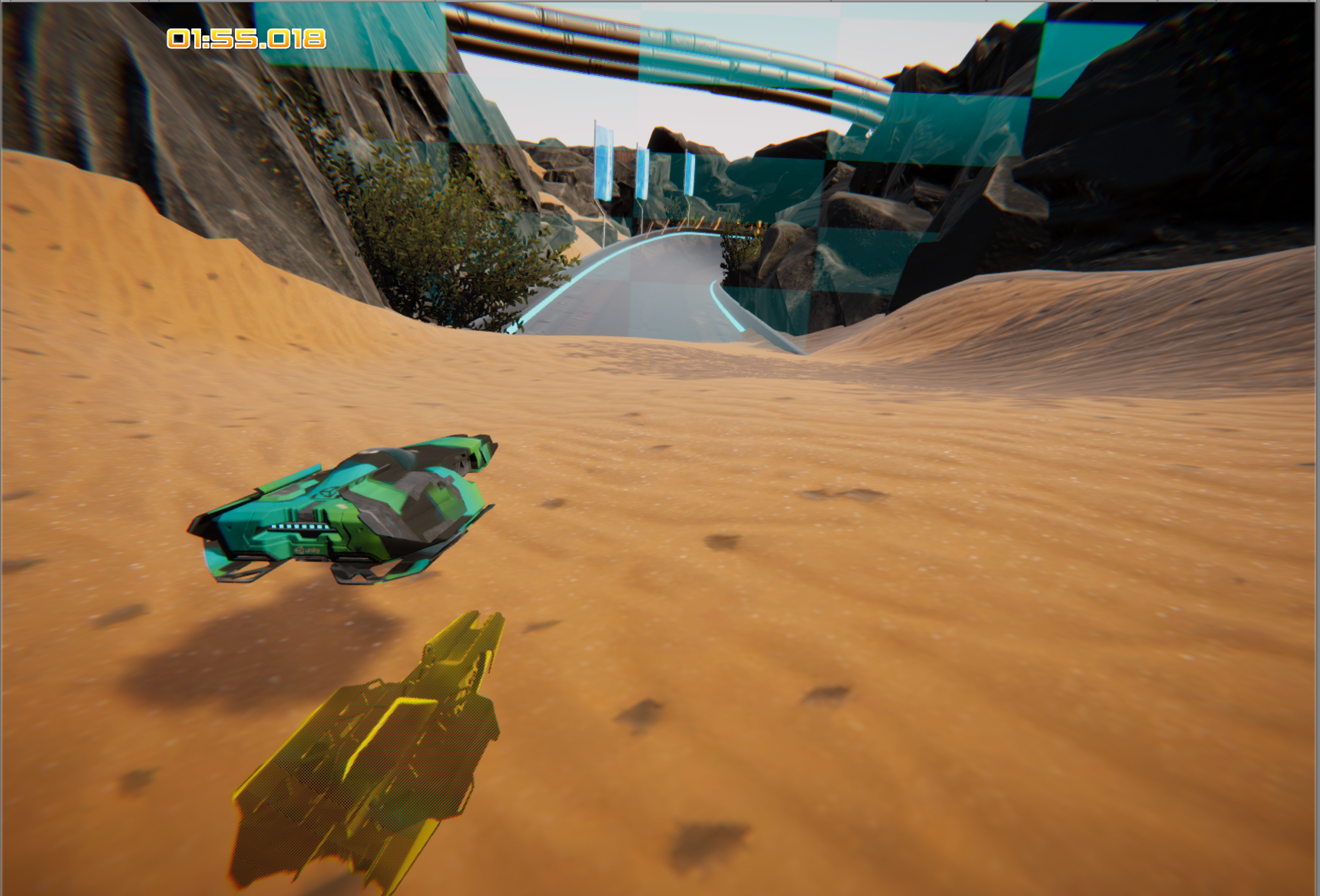
The Lightweight Render Pipeline (LWRP) is a legacy subset of Unity’s new Scriptable Render Pipeline implemented in version 2018.3. It enables users to extend Unity’s graphics pipeline with customized graphical effects, lending itself to artistically driven projects. Unlike ordinary shaders and effects, these passes are not camera dependent and can persist throughout the entire project without the need to set them up individually for each Scene.
Languages available:
1. Introduction
Unity versions 2019.3 (and future releases) use the new Universal Render Pipeline instead of LWRP. If you are developing on a version of Unity 2019.3 or above, please refer to guides on the Universal Render Pipeline. For the URP version of this tutorial, click here.
Note: the LWRP is not compatible with Unity’s standard renderer, or HDRP.
In this tutorial, we will be creating an x-ray effect where certain objects will render with a faint outline when they’re occluded by other geometry. To demonstrate, a mirror copy of a ship is rendered with the effect when it’s positioned below the ground, creating the illusion of a reflection (Figure 01).
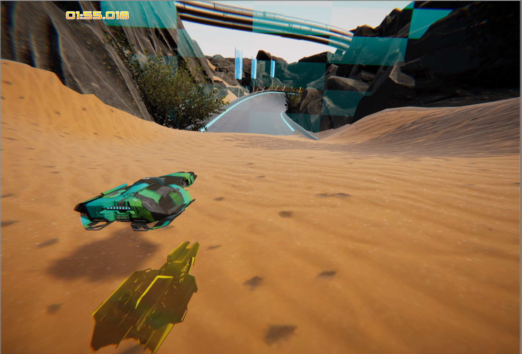
A more practical example would be the ability to see the original ship even if it’s occluded by objects. In this tutorial, we will accomplish just that.
2. Pipeline setup
To begin, we must set up our project to use the Lightweight Render Pipeline (LWRP).
- Import the LWRP package by navigating to Window > Package Manager and searching for Lightweight RP (Figure 02).
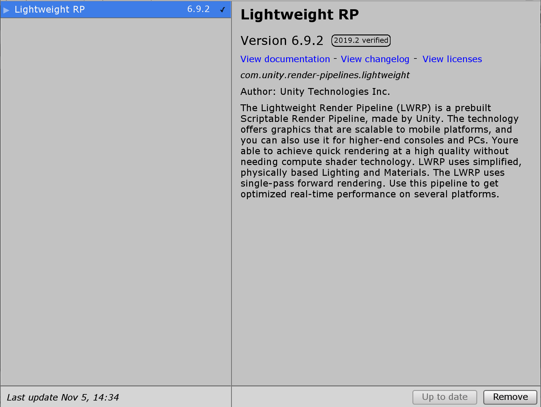
With our package installed, let’s create a new LWRP Asset.
- Right-click on the Assets folder and navigate to Create > Rendering > Lightweight Render Pipeline > Pipeline Asset.
Now we must tell our project to use the Asset we created.
- Navigate to Edit > Project Settings > Graphics. Under Scriptable Render Pipeline Settings, select the LWRP Asset (Figure 03).
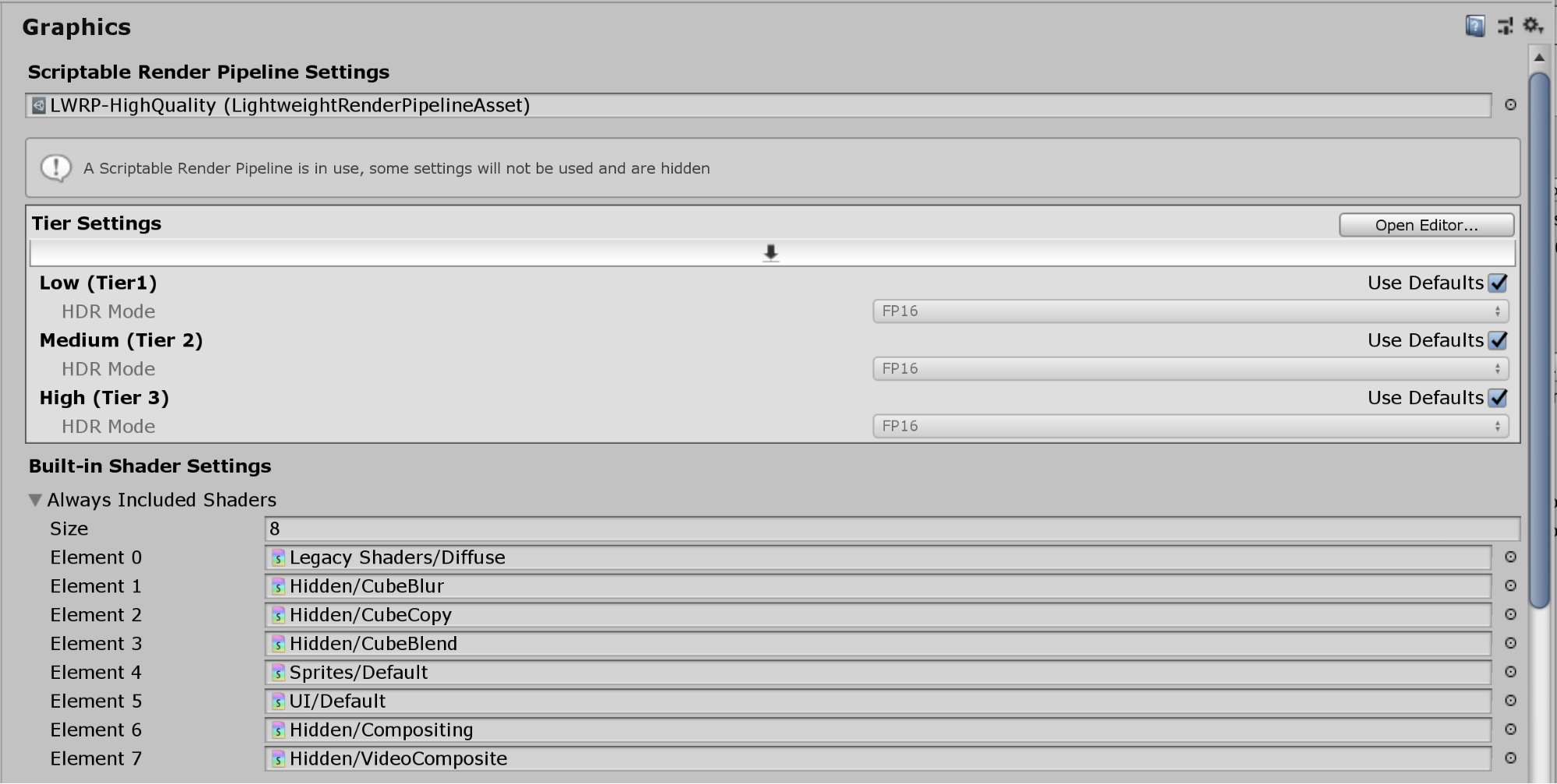
Next, we will create a custom Forward Renderer to extend the features of our render pipeline. This is necessary to customize rendering for objects on certain layers.
- Right-click on the Assets folder and navigate to Create > Rendering > Lightweight Render Pipeline > Forward Renderer. Let’s rename the renderer Custom Forward Renderer.
- Select the Pipeline Asset to view it in the Inspector. As we will be extending LWRP with custom effects, set Renderer Type to Custom, then drag the Custom Forward Renderer to the Data field (Figure 04).

You may notice that this has had no affect on your project. This is because our custom Forward Renderer hasn’t made any changes to the Scene. We’ll change that in just a bit.
3. Creating the Shader and Material
Our goal is to have an object appear translucent when it’s occluded by another object. In this step, we will create the translucent x-ray effect using Shader Graph.
- Right-click under the Project tab and navigate to Create > Shader > Unlit Graph to open the Shader Graph editor.
For those unfamiliar with Shader Graph, it’s a node-based editor introduced in Unity 2018.3. Shaders can be built visually by linking function nodes (for example, Noise and Dither) and operator nodes, like Multiplication, Modulo, Division, together into an output or master node. To get more acquainted with Shader Graph, please refer to Getting Started with Shader Graph.
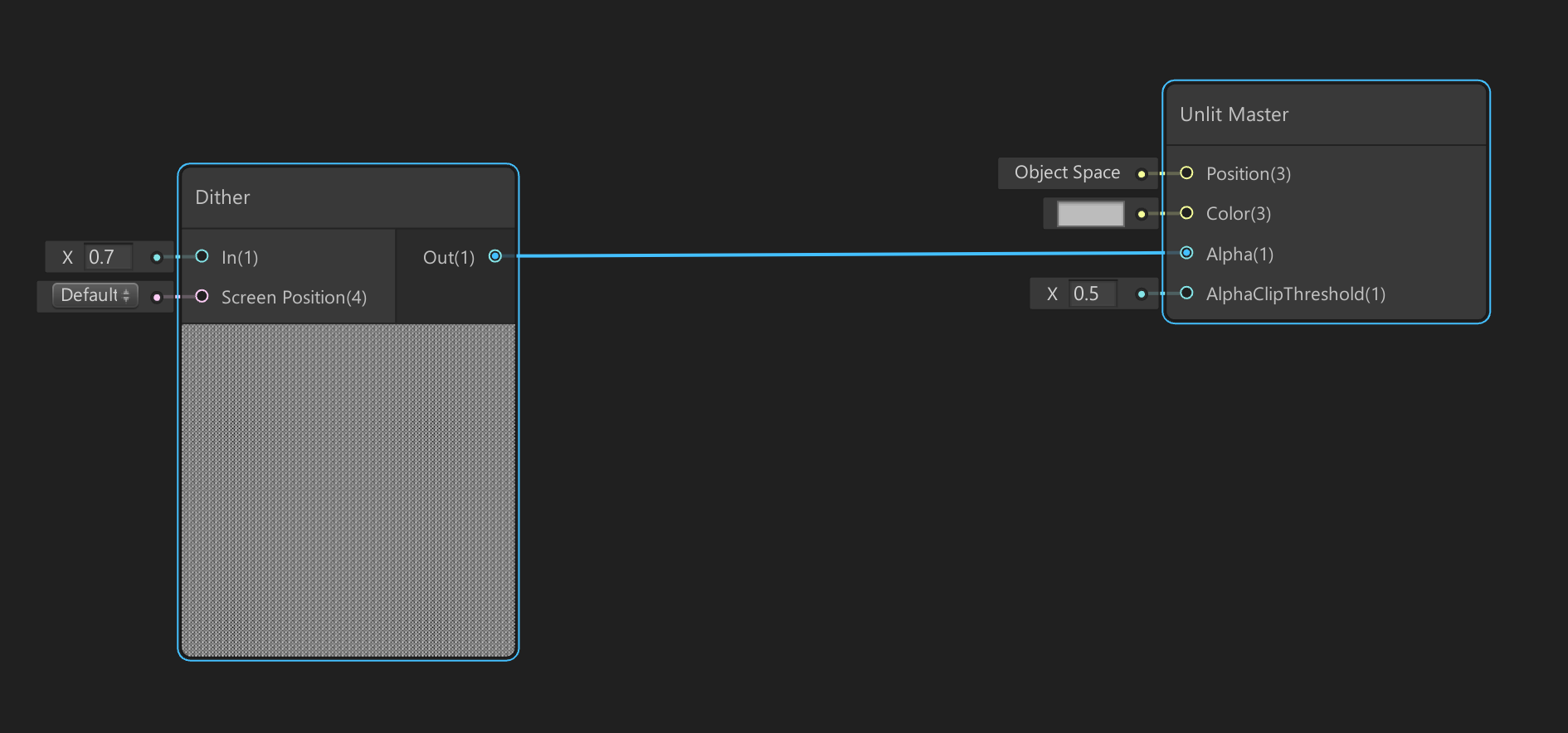
- Press the Space key to create a Dither node. This will form the basis for our x-ray effect by providing the Material with some texture.
- Click the drop-down next to the Dither node and set the In value to something between 0.5 and 1.0.
- Next, link this Dither node to the Alpha input of the Unlit Master node. This will make our dithered texture translucent (Figure 05).
- Press the Space key again to create a Fresnel Effect node. This node will provide reflective highlights to our Dither node (Figure 06).
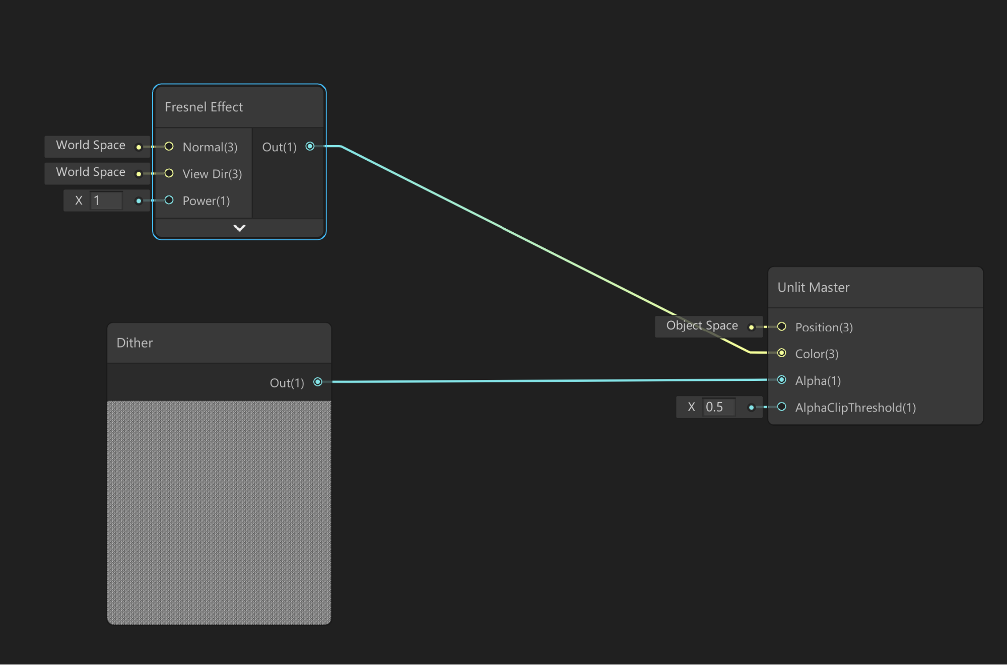
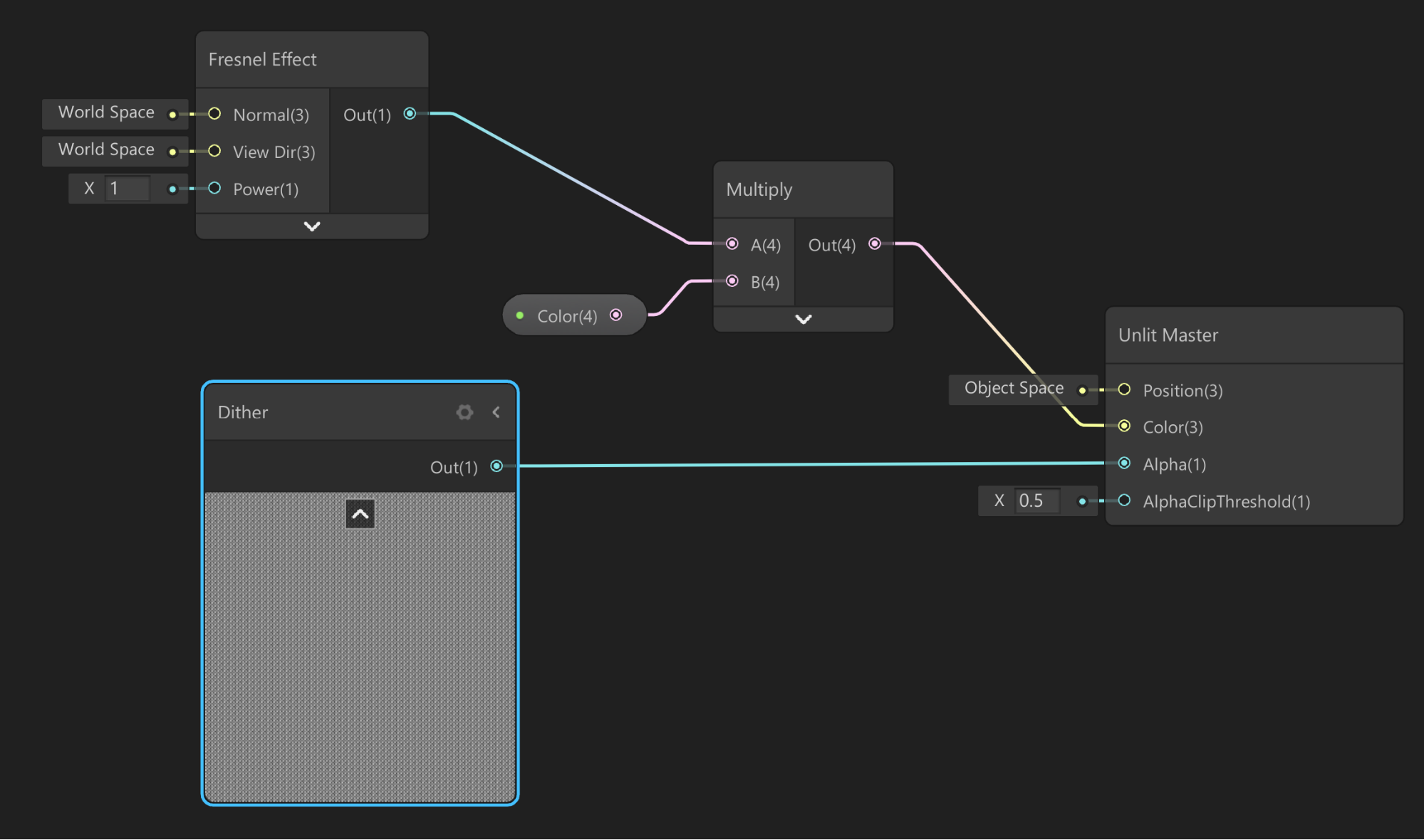
Linking the Fresnel Effect node directly to the output’s color will create white highlights by default. To customize the color of the highlights, we will use a Multiply node to blend the Fresnel with a color of our choosing.
- Add a Multiply operator node to the graph and link the output from the Fresnel Effect node to input A. In the Blackboard, create a Color node and set it to a color of your choosing. Then drag this to the graph and link it to input B of the Multiply node (Figure 07).
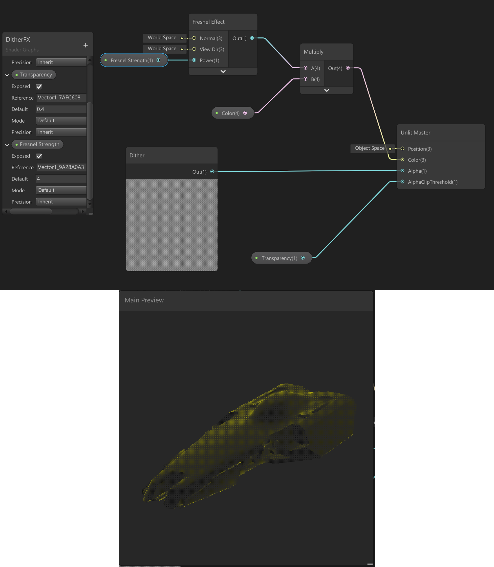
- To control the translucency of the effect, let’s return to the Blackboard and create a new Vector1. Rename it Translucency and link it to the AlphaClipThreshold of the output node.
- Lastly, create another Vector1 to control the strength of the Fresnel Effect and link it to the Power input. Higher values will concentrate the highlights more along the edges of the Mesh (Figure 08).
Now let’s apply this Shader to a Material.
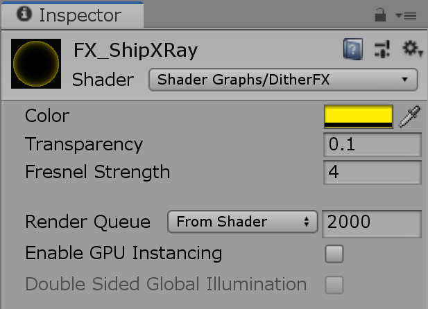
- Right-click under the Project tab and navigate to Create > Material, then set the Shader to the graph we just created (Figure 09).
4. Layer Masks and multipass rendering
Unity renders a Scene in multiple passes, or steps. Each step produces a single image. For example, one for Albedo (color information), one for Ambient Occlusion, and one for Normals. These images are then composited to create the final image we see on the screen. Separating each draw call into multiple passes gives us more flexibility over the final look of our image. We can assign objects to different Layer Masks, for instance, and explicitly define how the objects in that Mask are rendered in a new render pass.
This is exactly what we will do to implement the x-ray effect. Let’s begin by creating a new Layer Mask.
- Select the GameObject you want to render with this Material. Click the drop-down next to Layer, then select Add Layer.
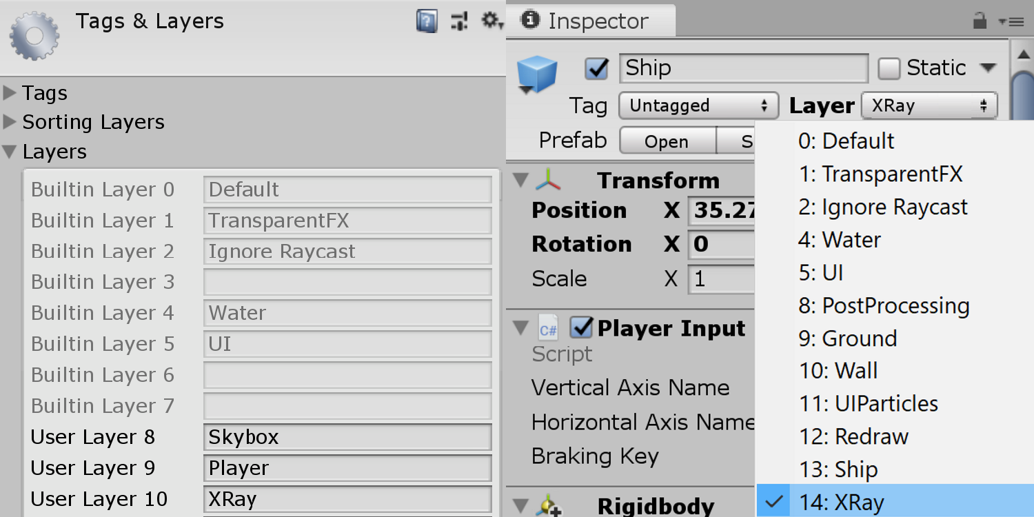
- In the Inspector, create a new Layer Mask called XRay.
- In the Hierarchy, select the GameObject again and click the Layer dropdown in the Inspector to assign the GameObject to the Layer we just created (Figure 10).
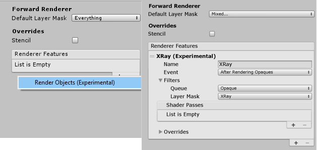
- Now let’s return to our custom Forward Renderer and select the drop-down beside Default Layer Mask. Deselect the XRay Layer we just created.
This will render everything in our Scene using the default Forward Renderer except for GameObjects on this Layer. “Why would we want to do this?” you might ask. As mentioned earlier, multipass rendering allows us to explicitly define how GameObjects on this layer will be rendered. This also means that it won’t be combined with previous render passes.
- Under Renderer Features, click the + symbol to create a new Render Objects renderer. Expand it and rename it XRay. Set the Layer Mask to the XRay Layer we created. Alternatively, we can create a new renderer feature by right-clicking under the Project tab and navigating to Create > Rendering > Lightweight Render Pipeline > Renderer Feature (Figure 11).
Next, we’ll create a Material Override to define how we want to render objects on this Layer. We want to render the object with our XRay Material when it’s obscured by other objects.
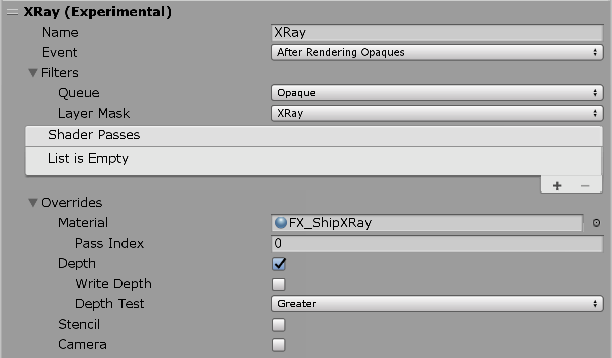
- Click the drop-down next to Overrides and drag the XRay Material we created into the Material slot. As our effect is dependent on the objects’ depth (or distance from the camera), we will tick Depth to obtain this information from the render pass. Lastly, set Depth Test to Greater. This will render the object with XRay Material when it’s obscured by another object (Figure 12).
With our current settings, the object is rendered with the XRay Material when it is obscured by parts of the environment (Figure 13).
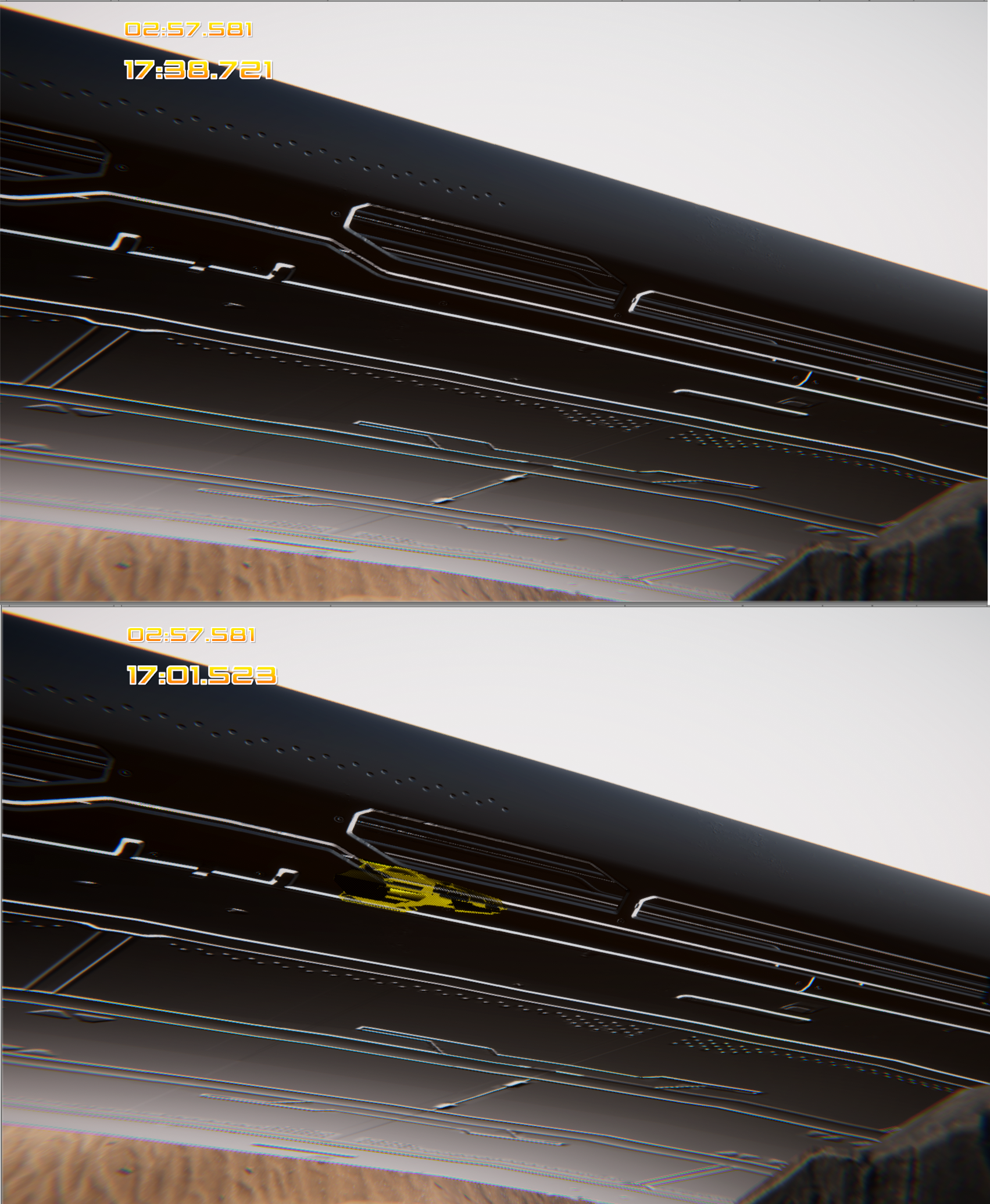
While this is what we want, it unfortunately renders the object invisible elsewhere. This is because we don’t have a renderer feature determining how objects on this layer should be rendered under other conditions (Figure 14).
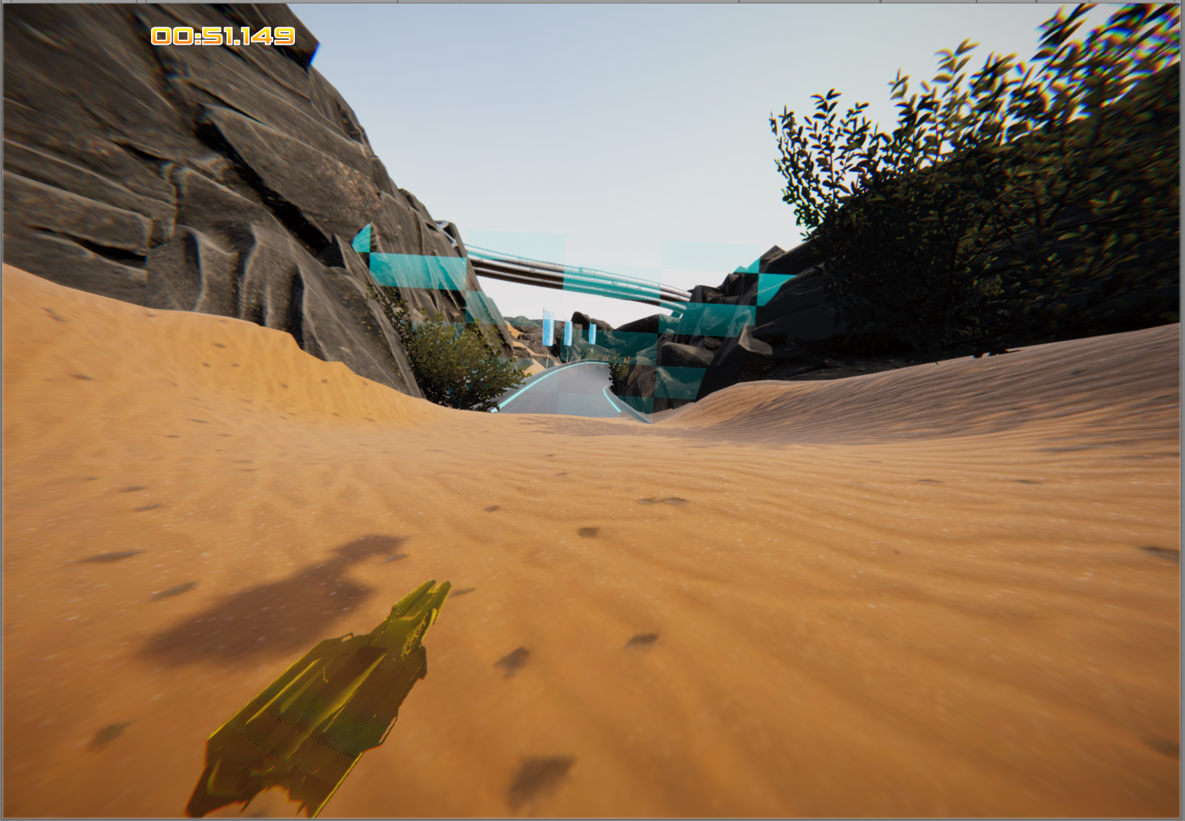
Let’s address this now:
- In our Custom Forward Renderer, create a new renderer feature and name it along the lines of Default. Set the Layer Mask to XRay, as you did in Step 17. In this instance we will not set any Material Overrides, as this renderer feature will simply render the object normally for cases where it is not obscured (Figure 15).
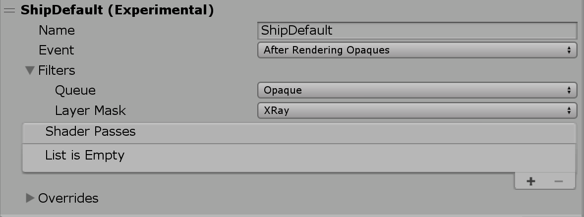
It is very important to note that this renderer feature must come last in the Hierarchy.
5. Conclusion
Through the use of Layer Masks, we can define how to render a specific set of objects using custom render passes in the LWRP. We also have the option of using Shader Graph to power the Materials used in each render pass instead of relying on traditional HLSL scripts in ShaderLab.