Modeling using Modeling Mode
Tutorial
intermediate
+10XP
30 mins
44
Unity Technologies
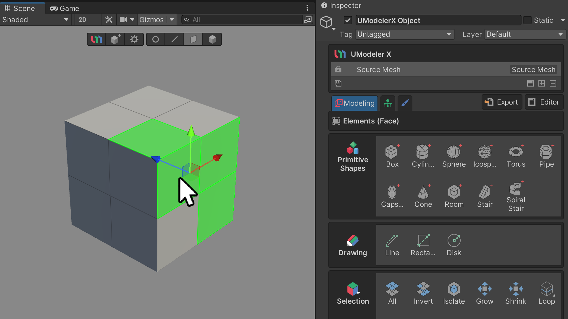
In UModeler X, a key feature for 3D model editing is the editable mesh. To utilize this feature, you must attach the'UModeler X Editable Mesh component to your GameObject. This addition unlocks various adjustable properties and icons in the Inspector window. UModeler X facilitates the creation and modification of editable meshes through three distinct modes and two specialized editors, enhancing customization of your UModeler X object. Among these, the Modeling Mode is central for mesh editing. This mode is organized into tools with diverse functionalities, properties that offer detailed tool settings, and groups that are composed of related tools. This tutorial will guide you through Modeling Mode, familiarize you with its various tool groups, and demonstrate how to modify a basic model using these tools.
Languages available:
1. Overview
An editable mesh is a mainstream 3D model editing property in UModeler X. To use the editable mesh, you need to add a component called UModeler X Editable Mesh to the game object. Once it's added, various properties, icons, and more can be accessed and modified in the Inspector window.
When creating and editing the current editable mesh, UModeler X has three modes and two editors that allow you to customize your UModeler X object.
Of the three modes, the Modeling mode is the primary mode for editable meshes, and its primary function is to edit meshes. This mode is broken down into tools, which serve multiple functions: properties, which are detailed settings for the tools, and groups, which are groups of tools.
In this tutorial, you will learn about Modeling mode by being introduced to the different groups in Modeling mode and using the tools to edit a simple model.
Additional resources
You can learn more about Modeling mode in the official Modeling Mode manual.
2. Before you begin
New to Unity?
If you’re new to Unity, welcome! The Unity Essentials learning pathway has been designed to help you get set up and ready to create in the Unity Editor. We recommend you complete this pathway before continuing with this UModeler X tutorial.
Update the Unity Hub
Before you begin to set up your Unity project, consider updating your Unity Hub to the latest release. If you are using an older version of the Hub, there may be differences between the guidance provided and your experience.
Review the Unity Editor basics
If you need to refresh your memory of the Unity Editor basics, you can take a moment to review Explore the Unity Editor at any time.
3. Create the first UModeler X object
In order to enter Modeling mode, you must first create a UModeler X object. Modeling mode serves as the starting point for utilizing UModeler X, enabling you to create and edit 3D models.
To create a UModeler X object, follow these instructions:
1. Select the UModeler X Create Object icon.

2. Locate the UModeler X Editable Mesh (Script) component in the Inspector window.
By default, this component is set to Modeling mode.
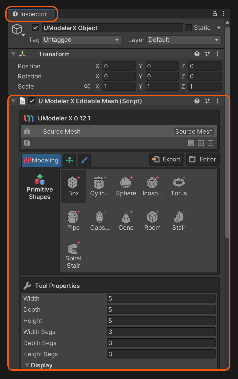
4. Learn about each group of modeling
Modeling mode is organized into three main categories: tools, their specific attributes, and tool groups.
These tools are classified into groups based on their functionalities and characteristics. Understanding the unique features of each group will not only accelerate your learning of the various tools but also make it easier to find the tool you need when you're actually working.
Element group
The Element group is located at the top of the Scene view and is a group of properties for each element (Vertex, Edge, Face, and Object).

Depending on the selection of elements, there are properties that are common to the Element group and properties that are specific to each element.
Primitive Shapes group
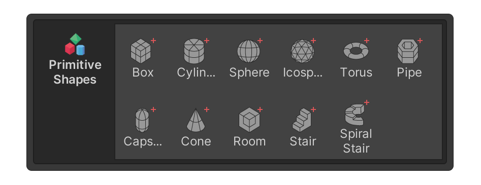
The Primitive Shapes group is a collection of tools that allow you to create meshes of primitive shapes.
Drawing group

The Drawing group is a collection of tools you can use to create planar shapes.
Selection group
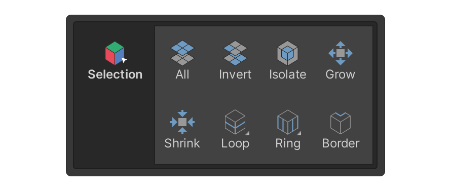
The Selection group is a collection of tools related to the selection of each element (Vertices, Edges, Faces, Objects).
Add group
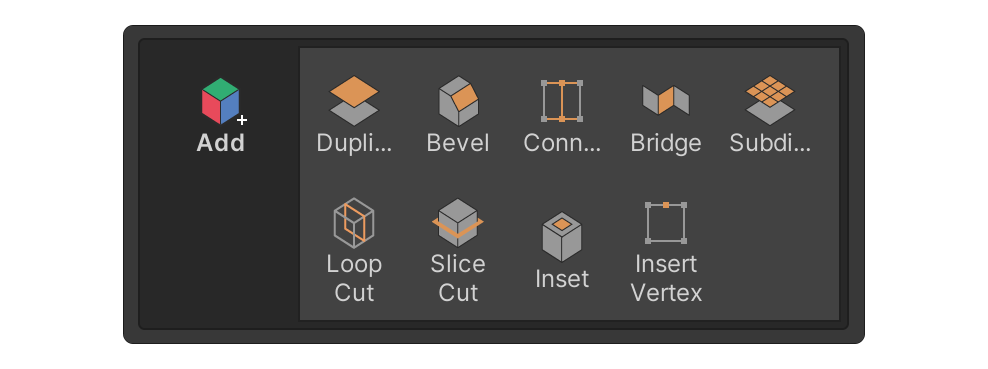
The Add group is a collection of tools that, when used, add elements such as vertices, edges, and faces to the model.
Remove group
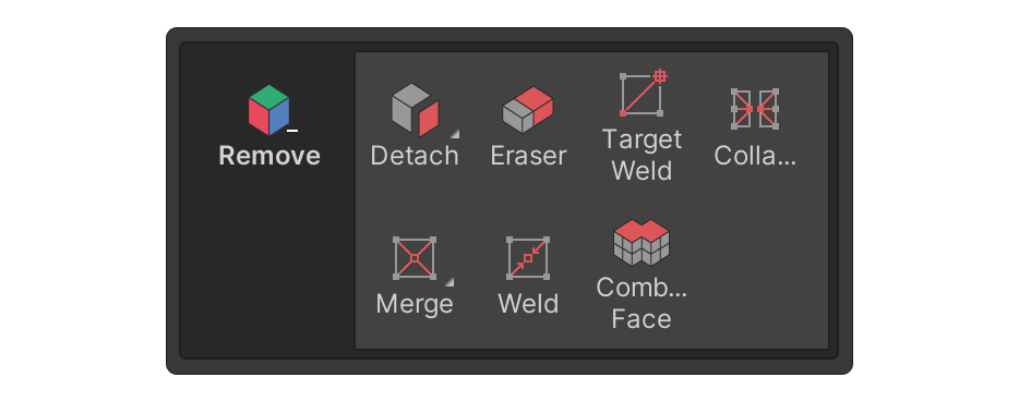
The Remove group is a collection of tools that, when used, remove elements such as vertices, edges, and faces from an object.
This group mainly contains tools that either delete the selected elements from an object or merge elements attached to an object.
Deform group

The Deform group is a collection of tools that modify the shape of surfaces using various sculpting brushes.
Surface group

The Surface group is a collection of tools for surfaces.
This group mainly contains tools that allow you to edit vertex color and material settings, and also contains tools that can be used to mark or unmark UV seams, which are essential for the unwrapping process.
Misc group

The Misc group consists of the Reset X Form tool, Flip tool, Pivot tool, and Local Settings tool. This group will be expanded in the future with more tools to enhance its usefulness.
Multiple Objects group

The Multiple Objects group is a collection of tools that can be used when multiple UModeler X objects are selected such as combining the selected objects or Applying the same operation to multiple objects simultaneously etc.
5. Modeling the basic shapes
To begin modeling, you must first create a mesh of basic shapes. The Primitive Shapes group and Drawing group contain tools for adding three-dimensional and planar shapes, respectively.
Using the Primitive Shapes group's tools
To create a box using the box tool, follow these steps. You will be able to learn the core of creating primitive shapes using UModeler X.
1. Select the UModeler X Create Object icon.

2. In the Inspector window, locate the UModeler X component.
3. Select the box tool from the Primitive Shapes group.
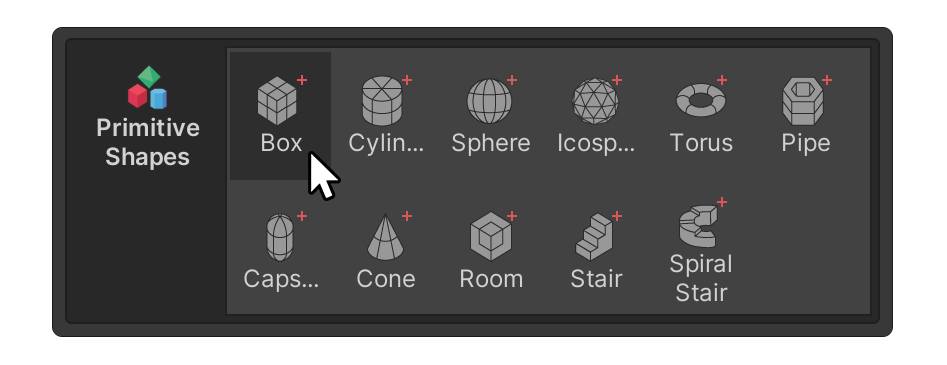
4. Click and drag around the scene to create the base of the box.
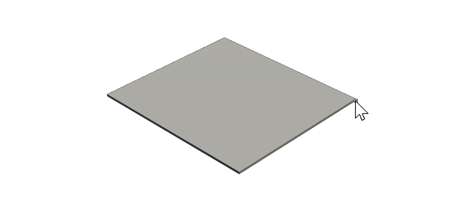
5. When you have the desired base, release the click and move the mouse cursor upwards to adjust the height.
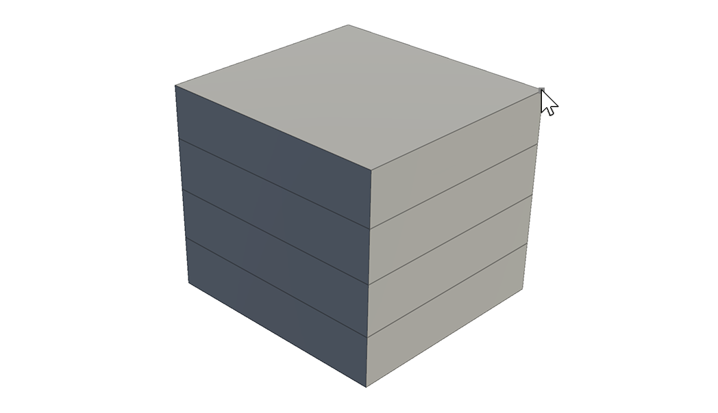
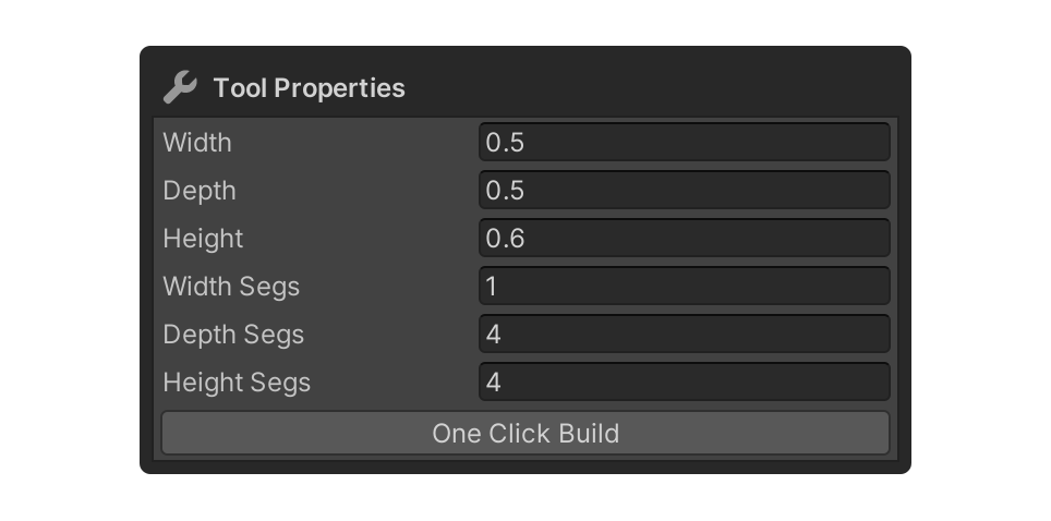
6. You can adjust the size of the box or how much of the face is split by changing the property values.
Using the Disk tool in the Drawing group
To create a disk on the floor, follow these instructions. Through this process, you will learn how to create 2D shapes such as rectangles or disks.
1. Select the Disk tool in the Drawing Group.

2. Click and drag around the scene to create a circular plane.
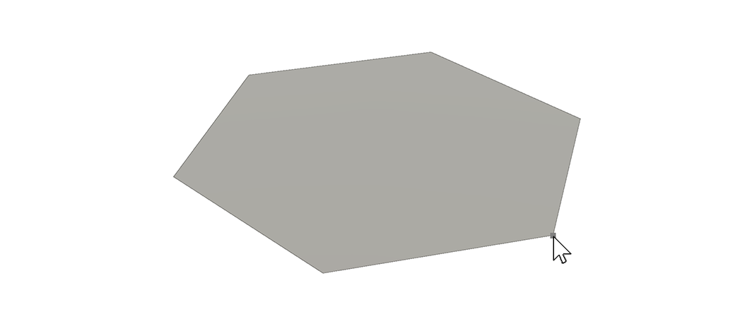
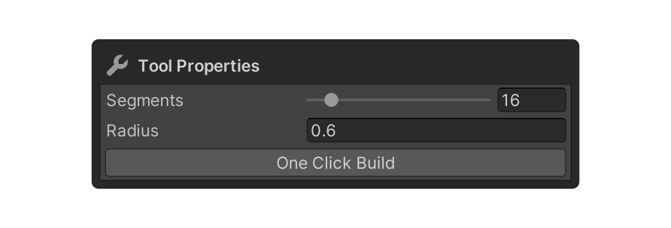
3. Try adjusting the properties of the Disk tool, such as Segments or Radius, immediately after you finish drawing a disk. Then, you can either start drawing another disk or switch to a different tool to complete the process.
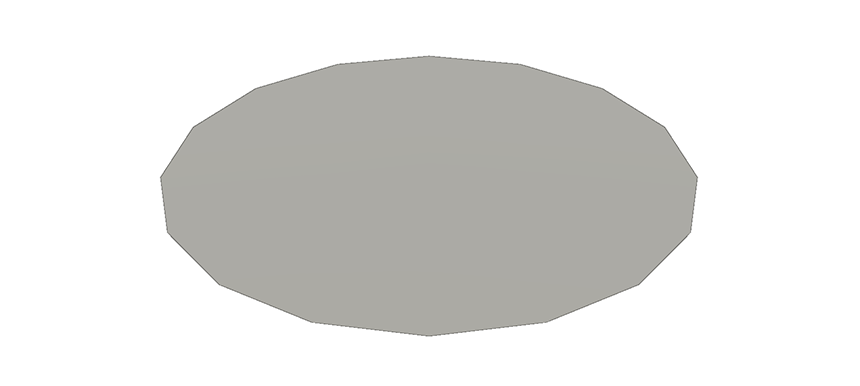
If you want to split the disk in half, you can use the Line tool.
4. Select the Line tool and select one of the vertices in the circular plane you created.
5. Select another vertex on the opposite side that you want to connect to, and the plane will split.
6. Modeling with Editing tools
The mesh of shapes created above can be edited with a number of editing tools. Below are instructions on how to use the most popular groups.
Selecting elements using the Selection group
You can also use the tools in the Selection group to select elements for editing, or to manipulate them with gizmos. To edit elements using the Selection group, follow these instructions:
1. Select a UModeler X object.
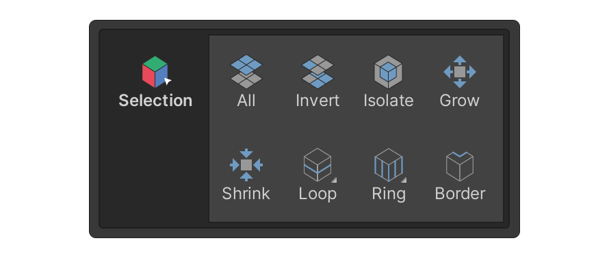
2. Select the Select Element button that corresponds to the element you want to select.
In this example, we’ve selected the Face tool.

3. Select an element in the scene.
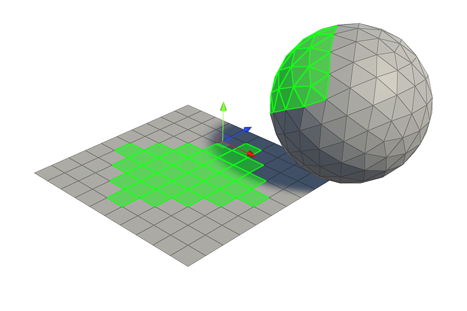
4. Select the desired tool in the Selection group.
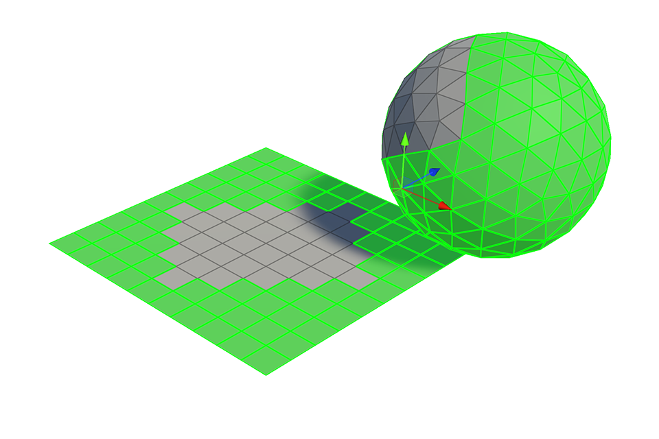
In this example, we've selected the Invert tool. In this example, this will select every other face than the one we originally selected.
Slicing faces using LoopCut tool in the Add group
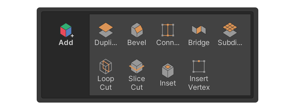
The Add group comprises tools that add elements like vertices, edges, or faces to an object through various operations. To create additional vertices, edges, and faces by slicing faces, follow these instructions with the LoopCut tool.
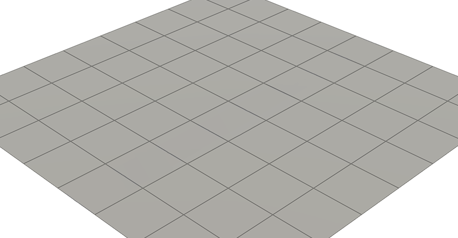
1. Prepare the model you want to edit. For this example, we'll use a model created using the Rectangle Tool.
2. In the Add group, select the desired tool.
In this example, we’ve selected the Loop Cut tool. The Loop Cut tool creates a connected edge that divides the face, based on the edge closest to the cursor.
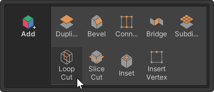
3. Hover the cursor over the desired location and click.
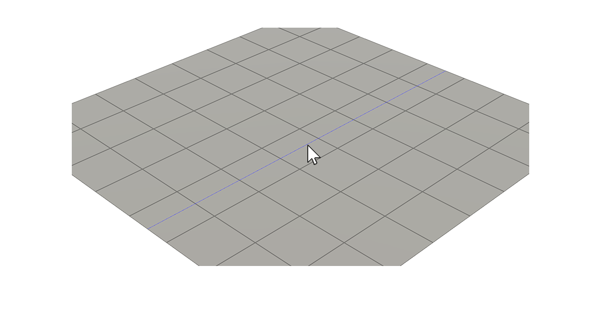
4. Adjust the properties, such as Split Number, Offset and Pinch etc., to the desired values.
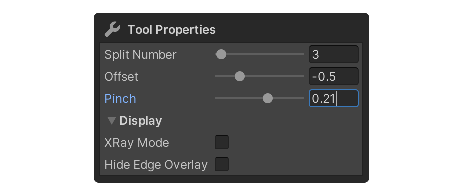
5. After adjusting the properties, start to do another LoopCut action or switch to another tool to complete the current LoopCut action.

Removing the selected faces using the Eraser tool in the Remove group.
The Remove group is a group that contains tools that allows you to delete selected elements or combine elements. To practice removing selected faces, follow these instructions.
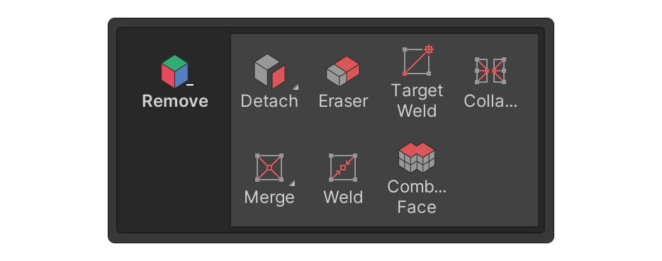
1. Select the Face tool.

Note: Depending on the tool, you may need to select the element in the scene first.
2. Select several faces in the scene.
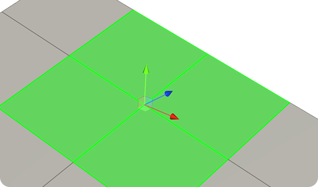
3. Select the desired tool in the Remove group.
In this example, we have selected the Eraser tool. The Eraser tool is the tool used to delete selected elements.
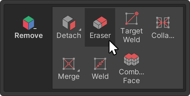
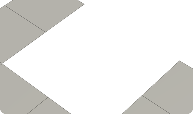
The selected elements will be erased!
Material settings using the Material tool in the Surface group
The Surface group contains tools for tasks such as vertex coloring, material settings, and marking or unmarking seams for UV unwrapping, among others.
To practice assigning materials to the selected faces, follow these instructions:


Note: Depending on the tool, you may need to select the element in the scene first.
In this example, we need to have some faces selected to run the Material tool.
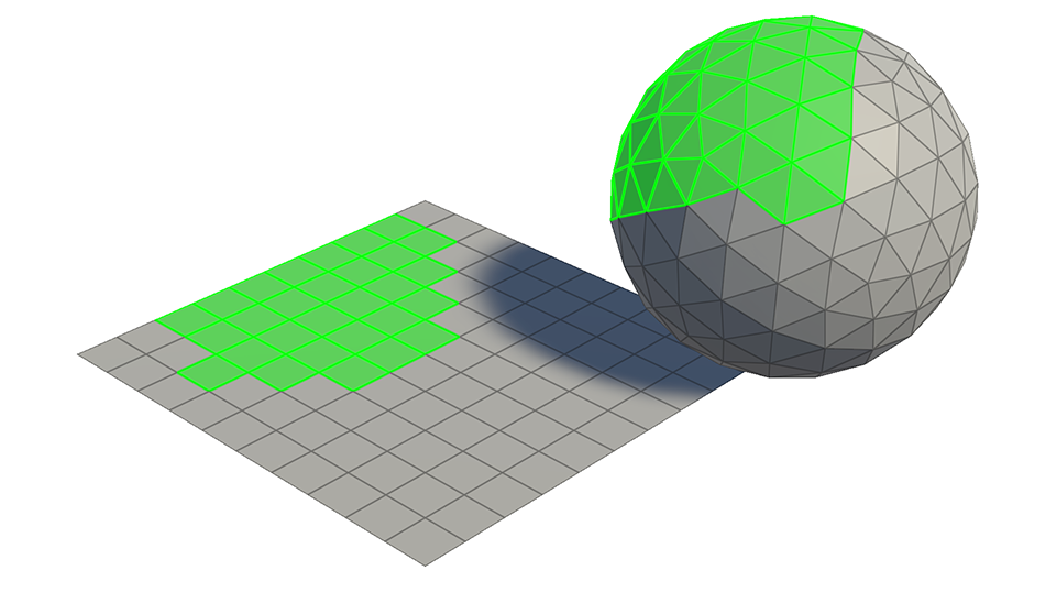
1. In the Surface group, select the Material tool.
The Material tool is the tool you use to edit materials for your object.
2. Select the Add Material button to add a material slot.
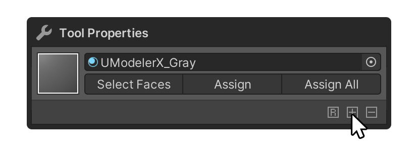
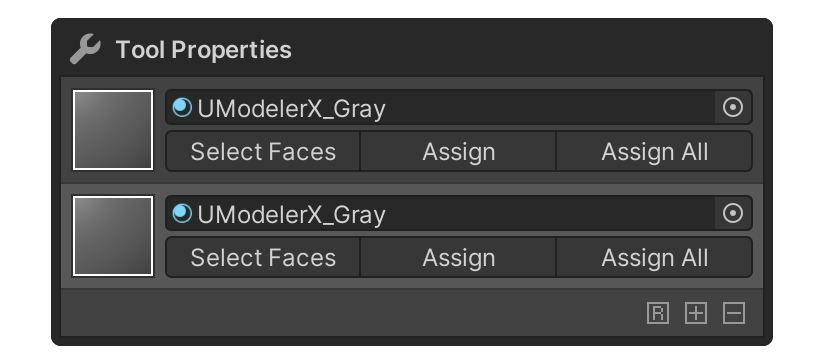
3. Add your desired material to the material slot.
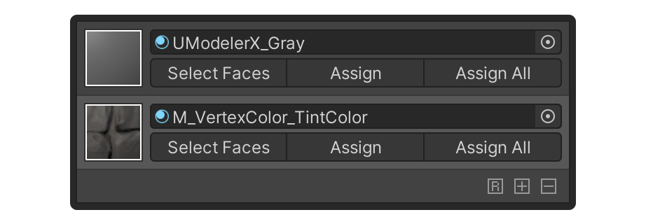
4. Select the Assign button for the material you want to assign to the face.
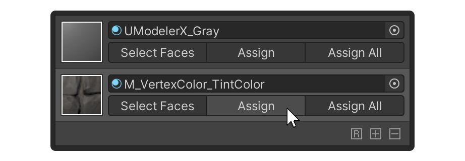
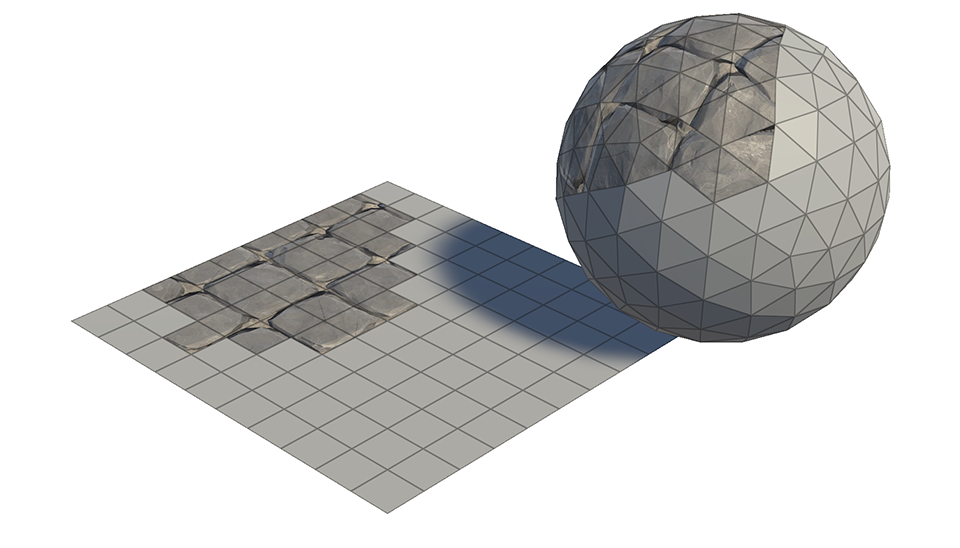
The material will now be applied to the selected face!
7. Next steps
Congratulations, you now understand the basics of Modeling mode. In the next tutorial, we'll transform models using the Modifier System.