
Optimize realtime lightmaps
Tutorial
intermediate
+10XP
60 mins
72
Unity Technologies
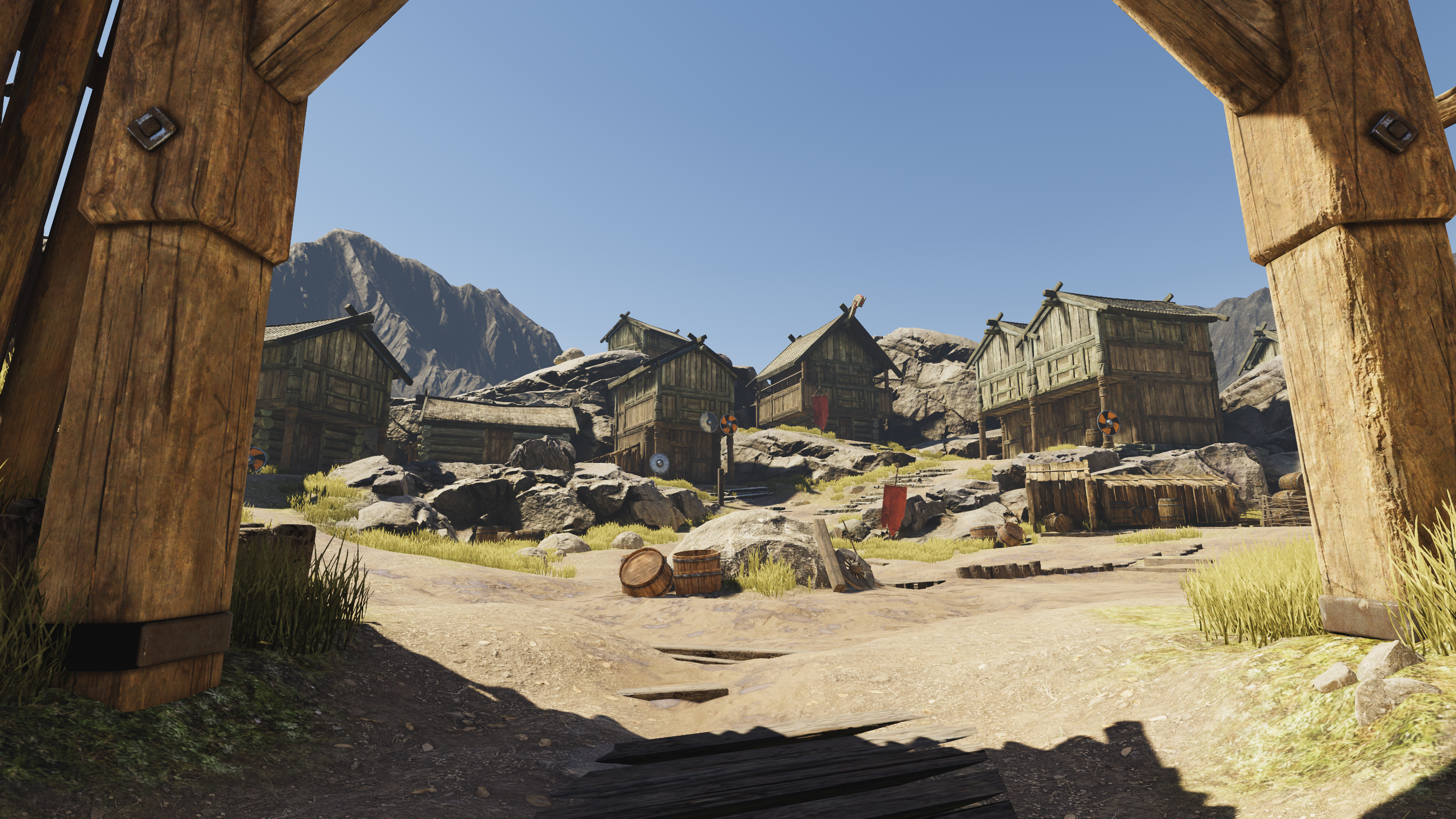
In this tutorial, you will improve the auto-unwrapped UVs generated by Unity’s Precomputed Realtime GI.
Languages available:
1. Overview
Now that you have excluded suitable objects from the lighting precompute, you can begin the work of reducing the number of remaining Charts by optimizing UV unwrapping.
Charts are created to encompass the UV lightmap coordinates of a Static Mesh Renderer. The number of Charts that an object requires is therefore largely determined by the number of UV shells (pieces) needed to unwrap the object in question. Unwrapping is always a tradeoff between distortion of the texel distribution on geometry faces, and the number of shells required for sufficient texture coverage.
2. Understanding Unity’s unwrapping algorithms
Unity’s sophisticated unwrapping algorithms will often achieve good results without your intervention; however, sometimes you need to provide a little guidance. It is therefore important that you understand the theory and process behind automatic unwrapping.
Let’s review three different examples of how the UVs on an object can be projected or unwrapped:
Example 1
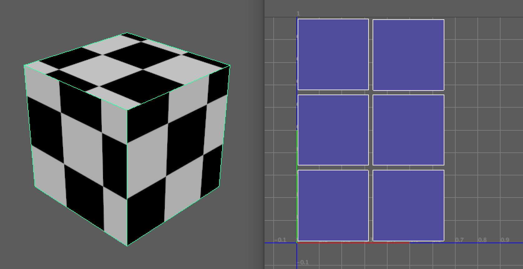
In this first example, the result is largely free of distortion. The checker pattern used as a texture is mapped in such a way that each tile of the texture remains square in aspect. If you imagine that this checkerboard was a lightmap (an ‘image’ of the lighting applied to the object), you would get a result that looked visually correct and without distortion.
However, you need to use six UV shells to get this coverage. As a result, you would get six Charts using Unity’s Precomputed Realtime GI system. Regardless of the size of the object, each Chart would require a minimum of 4x4 texels, meaning that this object would use at least 96 texels irrespective of resolution.
Example 2
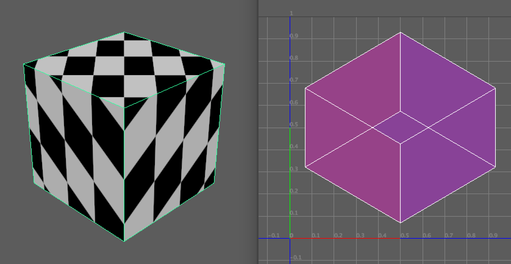
In the second image, there is a different problem. The object’s UV texture coordinates have been projected so that there is one complete UV shell covering all faces.
While this would be optimal in terms of the number of Charts required to cover the object, the visual results would be unacceptably distorted. You would likely see ‘smearing’ of textures applied across the surface of the object. The faces of the object also overlap in UV texture space — meaning that if you were referencing a lightmap, the lighting from one side of the object would be displayed on opposing faces. This method of unwrapping the object will not give you an acceptable result.
Example 3
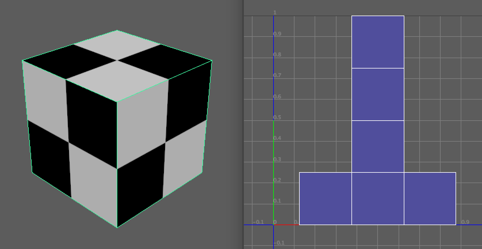
The third image shows an example of an ideal unwrap. The result is free of distortion: the tiles of the checkerboard texture have remained square in aspect. We have also succeeded in covering all faces of the object while only outputting one UV shell. This has been achieved by joining, or stitching, UV edges which correspond to contiguous geometry edges on the model.
If you think about this programmatically, what did we do to achieve an ideal unwrap?
- First, we have made our UV projections orthographically onto the object in order to create our individual shells.
- We then evaluated these shells for edges which are shared in the geometry of the corresponding object.
- Where shared edges were found, we moved and stitched those shells to the partner edges of their neighboring shell.
This is what Unity’s unwrapping algorithms attempt to do automatically with Static geometry.
3. Visualizing Charts
Before working to optimize your unwrapping and lightmap Charts, you need a way to visualize them in the Editor. Charts are generated during the unwrapping stage of the mesh import pipeline. For Precomputed Realtime GI, these Charts are then packed into atlasses during the Geometry stage of the precompute process. This is to ensure that they don’t overlap.
You can only see a preview of your Charts once the Geometry stage of the precompute has completed and the visualisation data has been saved.
Important: If you are working with version control as part of a team, please be aware that this information is cached locally. This means that a precompute must be carried out on your local machine before the various diagnostic Draw Modes become available.
There are two different approaches you can take to visualize the Charts.
Option 1: Use the UV Charts Draw Mode
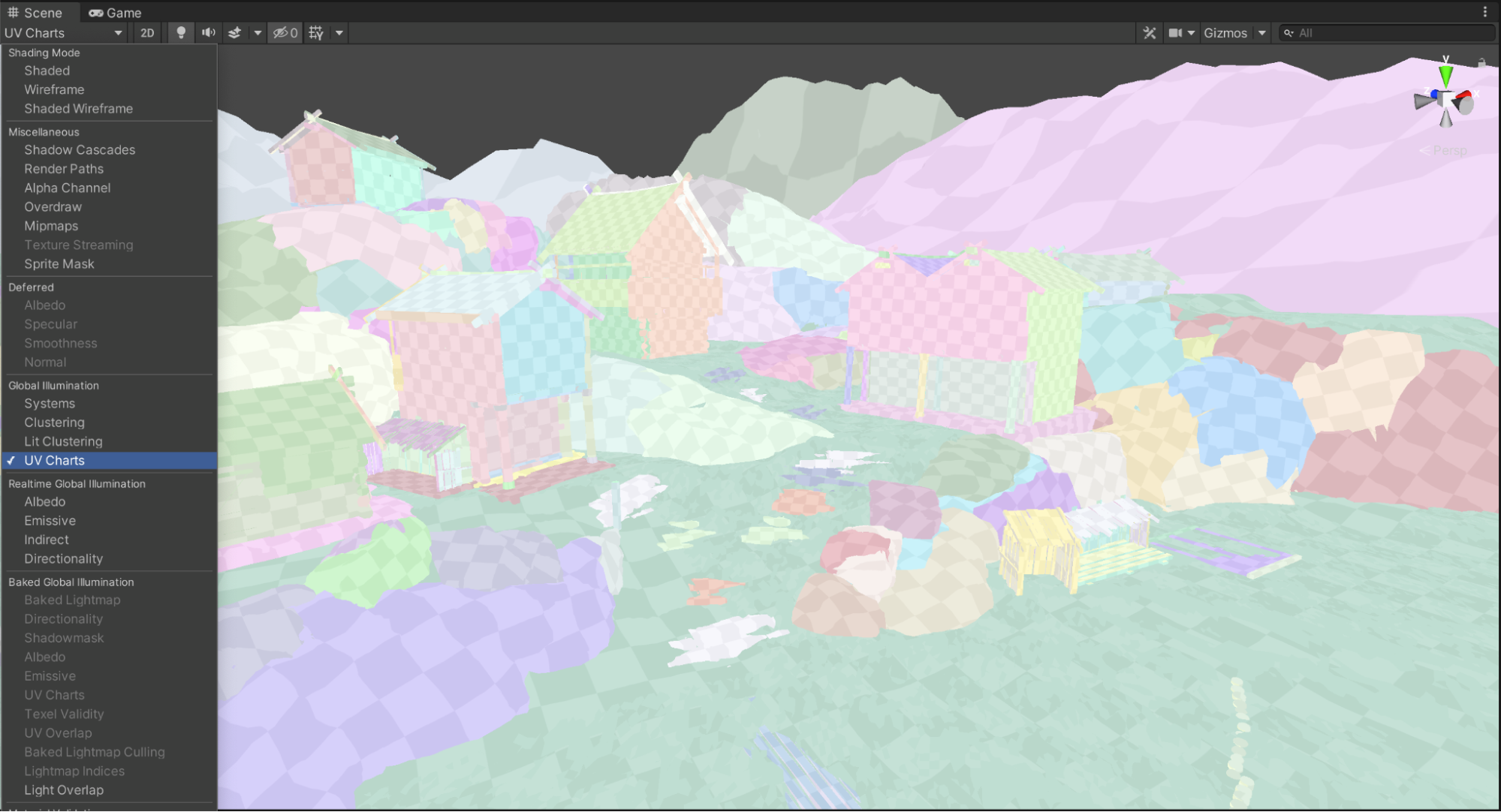
One way to quickly visualize your Charts is to use the UV Charts Draw Mode in the Scene view. Using this mode, Charts can be seen as different-colored panels overlaid with a checkerboard texture representing the corresponding lightmap resolution. To use this mode:
1. In the top left of the Scene view, use the Draw Mode dropdown menu to select UV Charts.
2. If you have Auto Generate mode enabled (Window > Rendering > Lighting Settings > Auto Generate), changes to unwrap parameters will be calculated automatically and the Scene view will be updated with the results.
Option 2: Use the Lighting window Preview pane
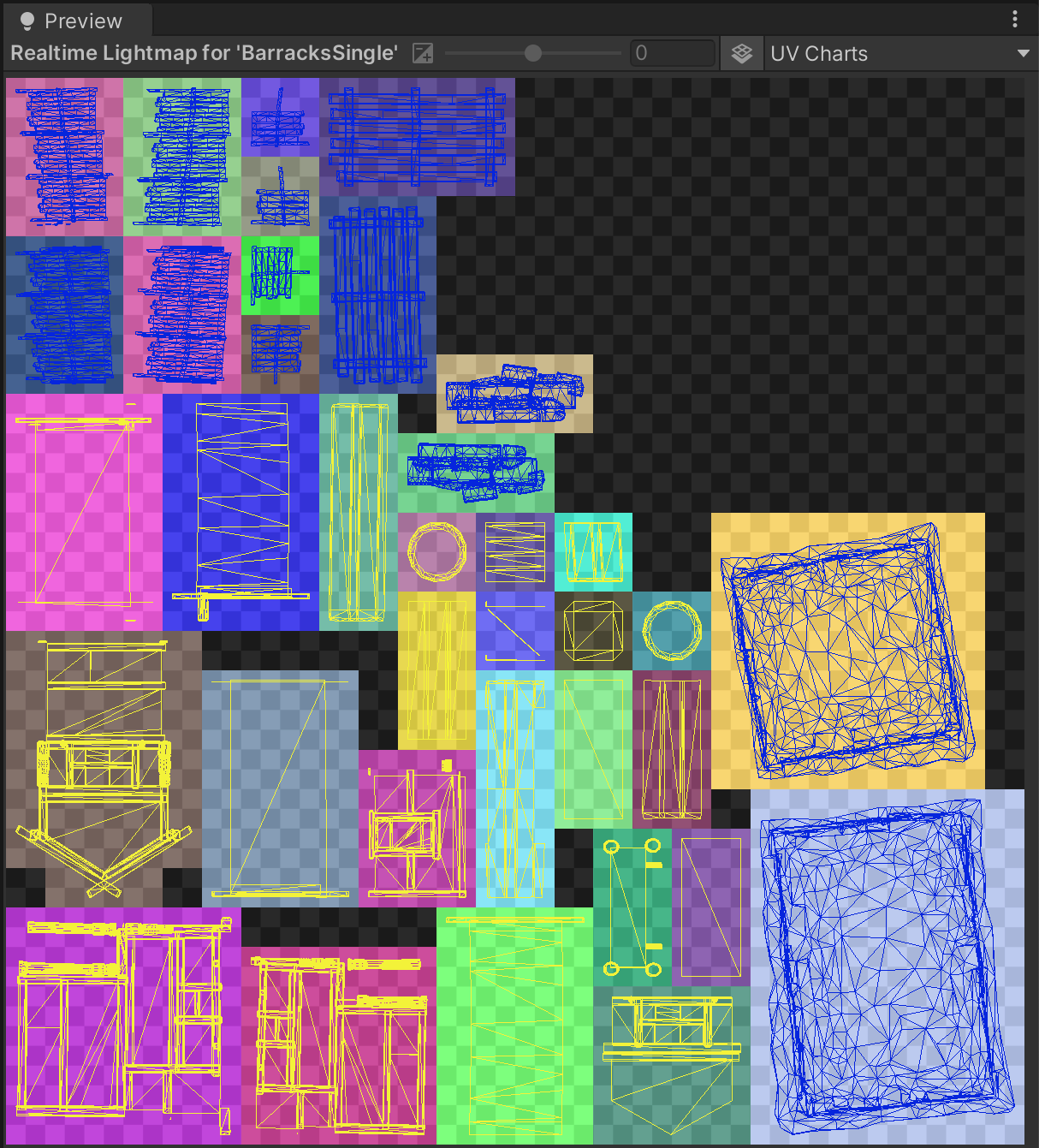
It can be easy to miss Charts in the Scene view when working with complex objects. By using the Preview pane in the Lighting window, you can view all the Charts used by an individual object. This can help you to more accurately assess the unwrapping of these objects, which will help you to reduce Chart counts in the scene.
To use the Preview pane:
1. In the Hierarchy, select the object that you wish to view.
2. Open the Lighting window (Window > Lighting) and select the Object tab.
3. In the Inspector window (Window > General > Inspector) unfold the Lightmapping header.
4. Expand the Realtime Lightmap foldout, and double-click the lightmap thumbnail.
5. In the top right corner of the Preview pane, choose UV Charts from the dropdown menu.
The number of Charts used by that object will be represented by colored squares overlaid with the corresponding UV coordinates in light blue.
4. Unwrapping parameters: Optimize Realtime UVs
There are a number of settings that you can tweak to optimize UV unwrapping. All of these settings are per-object. You can access these settings in the Lighting window:
1. Select the object that you wish to view in the Hierarchy window.
2. In the Inspector window (Window > General > Inspector), expand the Lightmapping foldout.
Optimize Realtime UVs
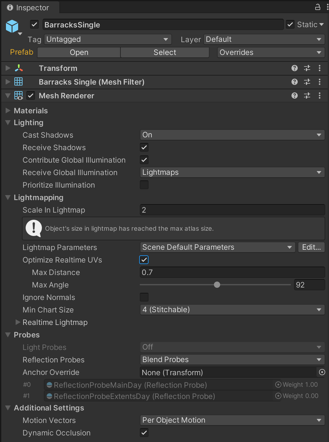
Unity’s automatic unwrapping algorithms allow users to author lightmap UVs within the Editor. You can use the Optimize Realtime UVs option to access these controls, which can be found under the Lightmapping foldout in the Mesh Renderer component.
Enabling this option exposes two properties: Max Distance and Max Angle.You will review these properties later in this tutorial.
In some cases it may be impossible to get an ideal unwrap using the auto unwrapper. You may end up with too many Charts or unacceptable distortion in the lightmaps (visualized as stretched checkering when in the GI Charts Draw Mode). In these cases, it may be necessary to manually author UVs in the UV01 channel of your model file. This is work that needs to be done while in your chosen content creation package.
If this is the case, disable the Optimize Realtime UVs setting to force Unity’s unwrapping algorithms to preserve the shape of the UV shells defined in your model’s UV01 channel.
It is important to note that these shells will always be repacked to save lightmap space. It is the manner in which the shells are unwrapped, individually, which will be preserved rather than the shell’s position within the lightmap.
Important: You must be cautious when using this approach. In cases where your lightmap UVs contain a large number of UV shells, this option can actually increase precompute times. This is because the UV merging step offered by Unity’s auto unwrapper is bypassed and the manual UV layout is preserved. Remember that the desired outcome is as few UV shells — and therefore as few Charts — as possible, while keeping an acceptable level of distortion.
5. Unwrapping parameters: Max Distance
Unity’s unwrapping algorithms attempt to simplify lightmap UVs by moving shells and stitching UV edges together. UV shells will only be considered for this operation if shells are within the distance defined by Max Distance. This range is defined in Unity’s world space units. Remember that in the example scene, we are assuming that a unit is 1 meter.
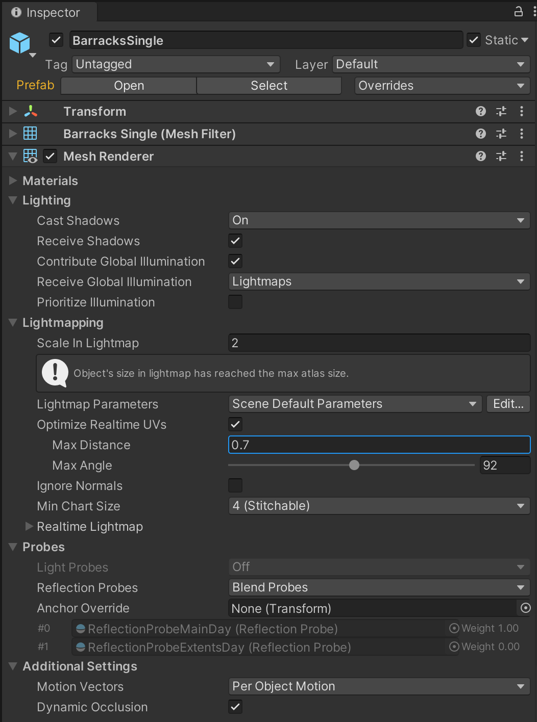
In many cases, the default value of 0.5 units will give acceptable results. For particularly large objects with large faces, it may be necessary to increase this value. This is to prevent suitable candidate UVs from being excluded from selection by the stitching algorithm.
Increasing the Max Distance will often reduce the number of Charts required by the selected object. Decreasing this value is useful in situations where there is visible stretching of lightmap texels and we may actually need more Charts in order to get the required texel coverage. The results of these changes can be easily assessed using the checkerboard overlay in the UV Charts Scene view Draw Mode. Finding the right balance can often require a little experimentation.
6. Unwrapping parameters: Max Angle
Lighting UV shells are also evaluated for stitching based on the angle between neighbouring faces of the corresponding mesh. Max Angle defines the maximum angle permitted between faces sharing a UV edge and is calculated using the internal angle. If the angle between the backfaces is greater than this amount, these UV shells will not be considered for stitching.
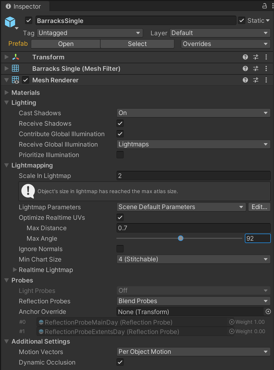
Increasing this value will make it more likely that lighting UVs will be combined by Unity’s unwrapping algorithm. Max Angle can therefore be a good way to reduce the number of Charts required by a selected object. However, sometimes stretched lightmaps can occur when this tolerance is too relaxed. Decreasing the Max Angle will make the unwrapper less likely to combine UV edges, which will result in more Charts but less distortion.
Again, using the checkerboard overlay in the UV Charts Scene view Draw Mode is a good way of assessing the suitability of the values you are using.
7. Unwrapping parameters: Ignore Normals
In certain cases, the mesh importer may decide to split geometry. This will also affect Charts. For example, if a mesh has an extremely high triangle count it may be more performant for Unity to split it into separate sub-meshes. Often this is for hardware specific requirements, such as reducing the number of triangles in each draw call. Where these splits occur is decided based on areas where there is large variance in the normal angle between adjacent mesh faces, such as hard edges.
Splitting meshes in this way happens during the mesh import process for your models. Charts can potentially be split during this process as edges that fall within a Chart may be separated, resulting in multiple shells which in turn will require additional Charts.
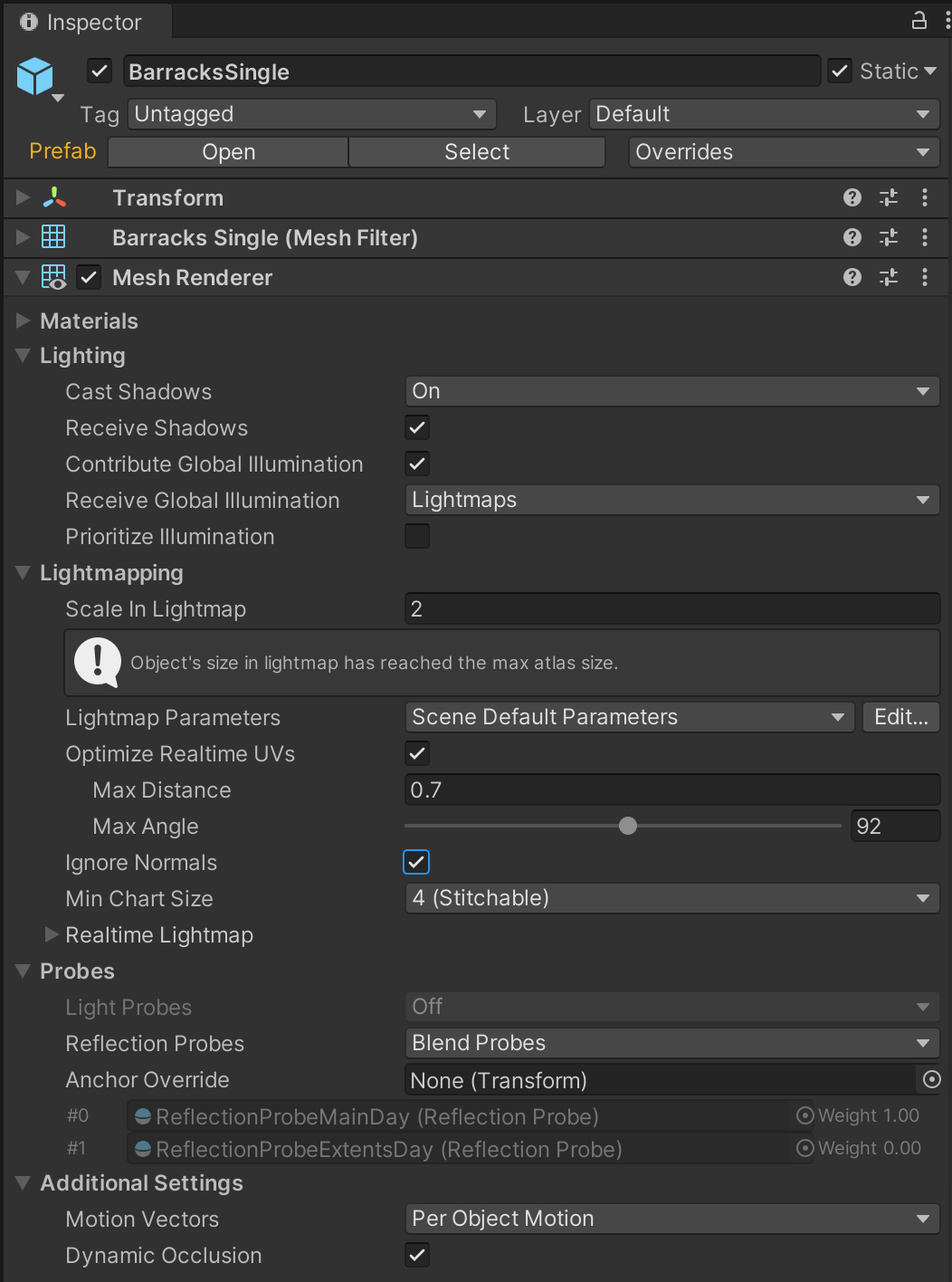
Sometimes it is not desirable to split your Charts in this way. The resulting increase in the number of Charts may be detrimental to precompute times, and lighting seams can cause unwanted visual artefacts in the resulting lightmaps. In these cases, enabling the Ignore Normals property will prevent the Charts being split for Precomputed Realtime GI lighting.
Note: Only Precomputed Realtime GI is affected by this option. Splits in the selected meshes are still preserved for other uses in Unity.
8. Optimize precompute time: Isolate objects of interest
Complex scenes can contain hundreds — even thousands — of Static objects. Generating the Chart atlases for all these objects can result in slow lighting precomputes and this can negatively affect the speed with which you are able to iterate on your scenes.
When experimenting with unwrap settings for objects, sometimes it can be useful to isolate an object of interest in an empty scene where you can iterate quickly with minimal precompute times. The unwrap settings you determine can then be taken back and applied to other objects of that type in the original scene. Working in this way can add up to big time savings when you are preparing scenes for lighting.
Let’s isolate a house object as an object of interest:
1. Open the LightingTutorialStart scene included in the example project.
2. In the Hierarchy, select one of the GameObjects called HouseBig02. These are grouped under Environment > Structures > Houses.
3. Copy this object to the clipboard by selecting Ctrl+C (Cmd+C on macOS).
4. Create a new scene by selecting Ctrl+N (Cmd+N on macOS).
5. If prompted to save your changes, select Yes if you are happy with your current scene progress or No if you wish to discard it.
6. In the newly created scene, paste HouseBig02 from the clipboard by selecting Ctrl+V (Cmd+V on macOS).
7. Open the Lighting window (Window > Rendering > Lighting Settings) and then select the Scene tab.
8. Enable the Auto Generate property to turn on Auto precompute mode.
9. Optimize precompute time: Review the object’s UV unwrap settings
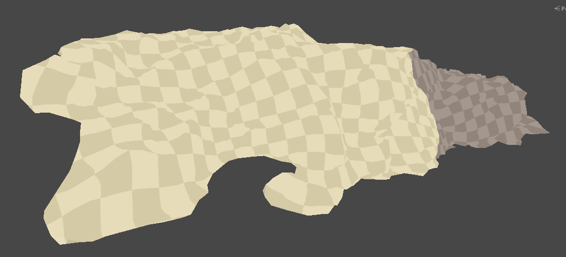
When configuring unwrap parameters, the ideal outcome is to find a combination of values that results in the lowest number of Charts while having the least lightmap distortion. Remember that distortion is visualized as stretching of the checkerboard texture applied to objects in the Scene view when UV Charts Draw Mode is enabled.
The checkerboard pattern can be used to visualize lightmap texel distribution. Notice in the example below that the checkerboard is relatively consistent across the model — meaning that there is little lightmap distortion.
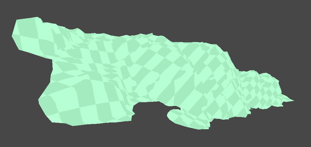
In this second example, the next example the stretching and warping of the checkerboard indicates that there is some inconsistency in the distribution of lightmap texels.
Let’s apply what you have learned about UV unwrapping to optimize precompute times on an object in the tutorial project:
1. In the Hierarchy, select the HouseBig02 GameObject.
2. In the Inspector window (Window > General > Inspector) unfold the Lightmapping header.
3. Expand the Realtime Lightmap foldout, and double-click the lightmap thumbnail.
4. In the top right corner of the Preview pane, choose UV Charts from the dropdown menu to review how the object is unwrapped.
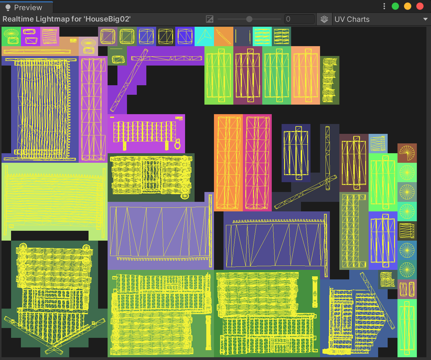
HouseBig02 is a fairly complex object within our scene, which may justify the use of multiple Charts. However, we may still be able to reduce this number by modifying our unwrap settings.
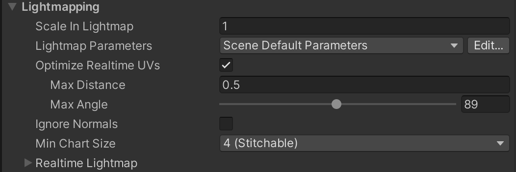
10. Optimize precompute time: Adjust the Max Distance
There is no one-size fits all solution for unwrapping objects. Unity’s unwrapping algorithms attempt to make sensible decisions based on appropriate defaults, but with some user guidance, it may be able to achieve a more optimal result.
Decrease the Max Distance
Let’s start by decreasing the Max Distance:
1. In the Hierarchy, select the HouseBig02 GameObject.
2. In the Inspector window (Window > General > Inspector) unfold the Lightmapping header.
3. Enable Optimize Realtime UVs.
4. Set the Max Distance to its minimum value of 0.1.
The precompute process will begin. Following a brief calculation, you’ll see in the Preview area of the Lighting window that the number of Charts has noticeably increased. Checking the Scene view there seems to be little distortion, which is good. Unfortunately, however, this many Charts for an object of this complexity is unacceptable. Remember that more Charts means longer precompute times and reduced performance at run time.
Increase the Max Distance
Let’s try increasing the Max Distance value:
1. In the Hierarchy, select the HouseBig02 GameObject if it’s not already selected.
2. In the Inspector window (Window > General > Inspector) expand the Lightmapping foldout.
3. Set the Max Distance value to 10.
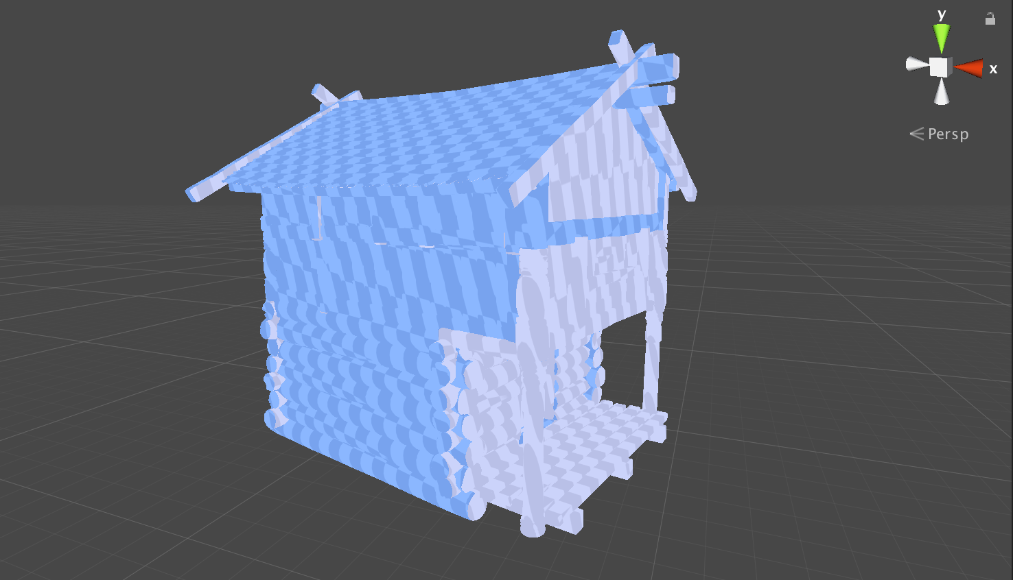
You now have the opposite problem. The number of Charts has decreased, but at the cost of introducing unacceptable distortion to the lightmaps. You can observe this distortion in the UV Charts Scene view Draw Mode. The distortion appears as streaking or stretching of the checkerboard overlay.
You now know that Unity’s unwrapping algorithm attempts to minimise the number of Charts by merging UV shells together. The Max Distance setting specifies the maximum distance, in worldspace, permitted between UV shells when they are considered for merging. If the shells are further apart than this value, they will not be combined.
In your experimentation:
- When you decreased the Max Distance, fewer UV shells were eligible for merging. This meant that more individual Charts remained at the end of the process.
- When you increased the Max Distance, UV shells that were very far apart in worldspace were then able to be merged. This resulted in fewer Charts, but this aggressive merging also caused warped lightmap UVs and therefore more distortion in the lightmap output.
Note that with large objects it can sometimes be necessary to increase the Max Distance in order to accommodate the size of faces within the mesh. Conversely, with smaller objects decreasing the Max Distance might yield better results.
Refine the Max Distance
For this example object, HouseBig02, a Max Distance value of 0.8 gives a good compromise between Chart count and distortion:
1. In the Hierarchy, select the HouseBig02 GameObject if it’s not already selected.
2. In the Inspector window (Window > General > Inspector), expand the Lightmapping foldout.
3. Set the Max Distance value to 0.8.
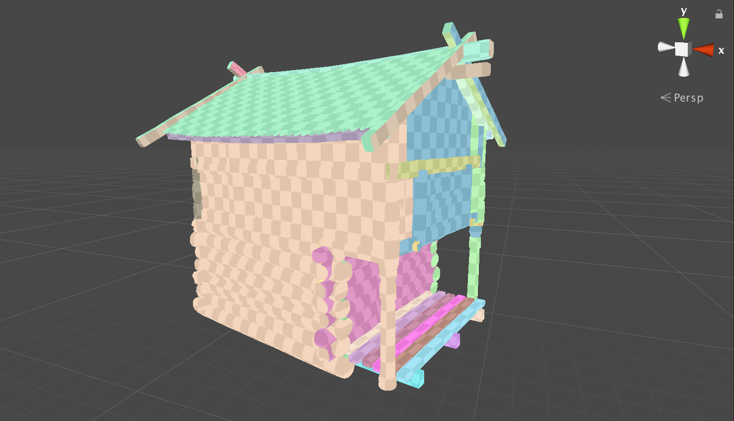
However, there are still some further improvements which can be made.
11. Optimize precompute time: Adjust the Max Angle
Now let’s review the Max Angle parameter. Like Max Distance, this value affects the UV merging step of Unity’s unwrapping algorithms. In addition to being tested for distance before UV shells are combined, the unwrapper also tests the angle between adjacent mesh faces. Only edges with an angle below this value will be considered for merging.
A smaller Max Angle means that fewer edges will pass the test. As a result, fewer UV shells will be merged and the number of Charts will increase. Conversely, a larger Max Angle means that the merging algorithm will be more tolerant of angles between faces. More UV shells are likely to be merged, the result of which will likely be fewer UV shells and therefore fewer Charts. As with the Max Distance, if unsuitable edges are combined due to overly wide tolerances, distortion may occur in the final lightmaps UVs.
Decrease the Max Angle
Let’s try decreasing the Max Angle:
1. In the Hierarchy, select the HouseBig02 GameObject if it’s not already selected.
2. In the Inspector window (Window > General > Inspector), expand the Lightmapping foldout.
3. Set the Max Angle value to 0.
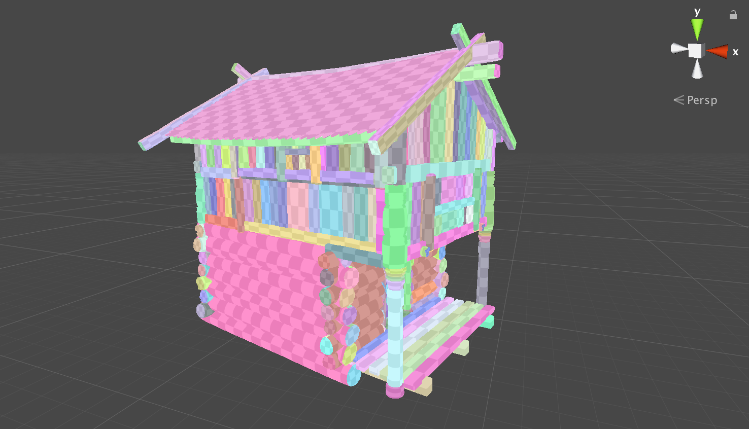
When you review the Preview area of the Lighting window, we’ll notice that the number of Charts created is unacceptably high. This is because you are only allowing a deviation of 0 degrees or less between faces before they are considered for merging. This almost certainly means that no UV shells will pass the test and therefore many Charts will remain following this merging process.
Increase the Max Angle
Next, let’s try increasing the Max Angle:
1. In the Hierarchy, select the HouseBig02 GameObject if it’s not already selected.
2. In the Inspector window (Window > General > Inspector), expand the Lightmapping foldout.
3. Slowly increase the Max Angle value and observe the effects of each change in the Preview pane of the Lighting window.
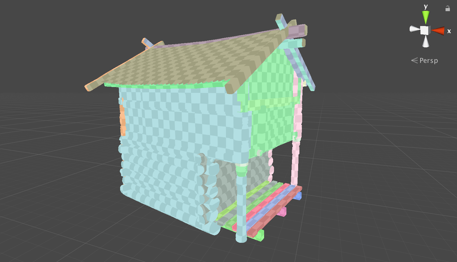
You should notice that the number of Charts decreases as the value goes up. This is because the angle permitted between mesh faces considered for merging is more tolerant. More UV shells pass the test and will be merged. Consequently, the number of lightmap UV shells is reduced and the number of corresponding Charts decreases. This approach is particularly helpful for reducing Charts on objects with rounded surfaces.
Refine the Max Angle
For this example object, HouseBig02, a Max Angle of 93 provides good results:
1. In the Hierarchy, select the HouseBig02 GameObject if it’s not already selected.
2. In the Inspector window (Window > General > Inspector), expand the Lightmapping foldout.
3. Set the Max Angle value to 93.
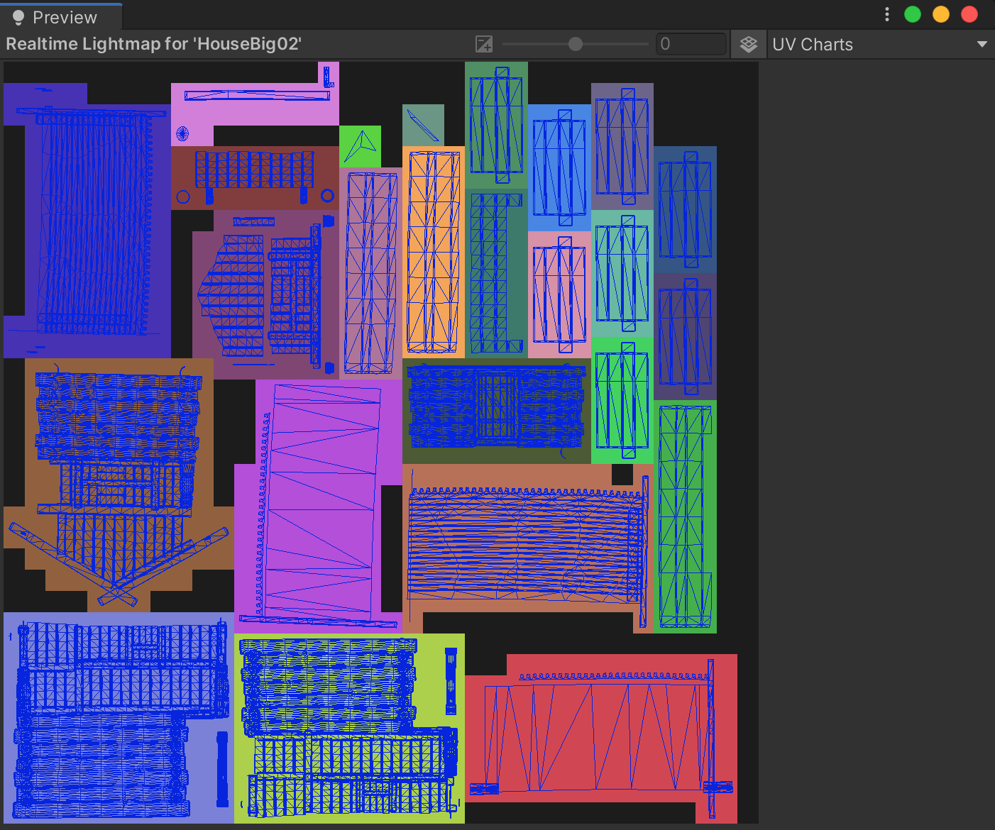
Notice how the number of Charts is reduced in the Preview area of the Lighting window following a brief precompute.
12. Optimize precompute time: Return to the working scene
At this stage, your optimized unwrap settings can be taken back into the working scene:
1. In the Hierarchy, select the HouseBig02 GameObject if it’s not already selected.
2. In the Inspector window, locate the Mesh Renderer component and select More options (⋮) in the top right of the component.
3. Select Copy Component.
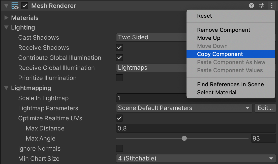
4. Open the LightingTutorialStart scene.
5. In the Hierarchy, find all the objects named HouseBig02.
6. Hold Ctrl (Cmd on macOS) and select each of the HouseBig02 GameObjects in the Hierarchy window.
7. In the Inspector, locate the Mesh Renderer component.
8. Select More options (⋮) in the top right of the component.
9. Choose Paste Component Values to apply the settings you previously copied.
The modest savings these settings give you can add up to much more significant optimisations when applied across a scene of several hundred objects.
13. Unwrap settings and Prefabs
Unwrap settings can be stored in a Prefab by applying them to any Static MeshRenderer component that lives within that Prefab’s hierarchy. Alternatively, unwrap settings can also be applied to individual GameObjects within the scene. Unwrap settings applied to an instance of a Prefab in a scene will override the settings stored within the Prefab. This way of working offers you some useful approaches to setting up scene lighting.
Per-Prefab settings
It is often useful to configure a default unwrapping and lighting setup for your Prefabs. If the Prefabs are to be instantiated numerous times, it can save effort to have the unwrapping for that object preconfigured rather than having to specify this repeatedly throughout the scene.
Per-Prefab Variant settings
As a part of the nested Prefabs feature introduced in the Unity 2018.3 release, it is now possible to create Prefab Variants. A Prefab Variant inherits properties from the Prefab that it is a variant of (which is called the base Prefab). You can override these properties for each prefab Variant created from a base. This can be a very useful way to configure default settings that are suitable for most scenarios and then override these settings in special situations.
For example, if a Prefab Variant will be seen up close within the playable area then it makes sense to use a higher fidelity setting on that Variant. If the Prefab Variant is far away, then it would not make sense to use your lighting budget maintaining the same resource-intensive settings. In that case, a better approach for you to take would likely be to lower the quality of the lightmaps and use more aggressive stitching parameters in the unwrap.
14. Apply unwrap settings throughout the scene
It is time to start applying what you have learned about Unity’s automatic unwrapping algorithm to the remaining Static geometry within the LightingTutorialStart scene. Working systematically, it should not take long to set up the scene for significantly improved precompute times:
1. Open the LightingTutorialStart scene included in the example project.
2. In the Hierarchy window, select the top GameObject found under Environment > Structures.
3. Copy the GameObject to an empty scene.
At this point, you should apply what you have learned about the unwrap parameters and feel free to experiment with different values. Remember to use the UV Charts Scene view Draw Mode in combination with the Charting mode of the Preview area of the Lighting window. This will enable you to find the right balance between lightmap distortion and the number of Charts required.
Exercise guidance
The LightingTutorialOptimal scene can be used as a reference in cases where you are unsure. Note that in some cases it may even be unnecessary to change the default unwrap values at all. The default values may actually provide the best outcome.
To complete this exercise:
1. Experiment with different values for the unwrap parameters until a balance is reached between number of Charts and lightmap distortion.
2. Copy the settings, return to the LightingTutorialStart scene and paste them into all other instances of the same GameObject. Multi-selecting all the corresponding objects in the hierarchy will enable you to use Paste Component Values to quickly apply the settings across multiple objects.
3. Repeat this process for every uniquely named GameObject in the Hierarchy view.
4. Once all of the GameObjects under the Structures group have been optimized, move onto the remaining Static geometry under the Rocks group.
Working methodically in this way, it should take you no longer than a few minutes to set the unwrap values for all of the Static geometry within your scene. The outcome of this manual preparation will be faster iteration when lighting the scene and better performance at run time.
15. Next steps
In this tutorial, you explored the role of unwrapping in reducing the number of Charts in your project, which can have a significant impact on lighting optimization.
Next, you’ll complete this learning experience by fine-tuning Lightmap Parameters in the Unity project.