
Simulating Weather with the VFX Graph
Tutorial
intermediate
+10XP
20 mins
(145)
Unity Technologies
In this tutorial, you will learn how to drive the shape and size of your particles over time using a velocity field to create the effect of a snowstorm.
Note: You can download the tutorial materials, located above the left side progress tracker, to work through the tutorial.
Resources
Languages available:
Overview Video
1. Introduction
This tutorial was verified with Unity 2019.4.9f1 LTS and Visual Effect Graph 7.3.1.
It is recommended that you complete the Introduction to the VFX Graph tutorial prior to working on this tutorial.
In this tutorial, you will learn how to drive the shape and size of your particles over time using a velocity field to create the effect of a snowstorm.
Before we begin creating our network within the VFX graph, it is good practice to study reference imagery of the effect you wish to create. By studying how the individual particles in a real-life (or fictional) system behave, you will have a sense of which Blocks and Nodes you will need to achieve a desired behavior.
With snow for instance, there are three key behavioral properties we can observe:
- Snow does not fall uniformly, it flows along the velocity of air and wind.
- Snow can appear more streaky the faster it moves.
- Snow falls at a variable intensity.
Fortunately, all three of these can be modeled in the VFX graph.
Throughout the rest of this tutorial, it is recommended to consult the glossary below when building your graphs to gain more in-depth knowledge of the Blocks we will use, and to gather new ideas for modelling other behaviors: VFX Graph Blocks Glossary
Let’s start by creating a new VFX graph and opening it in the graph editor.
2. Appearance and Initialization
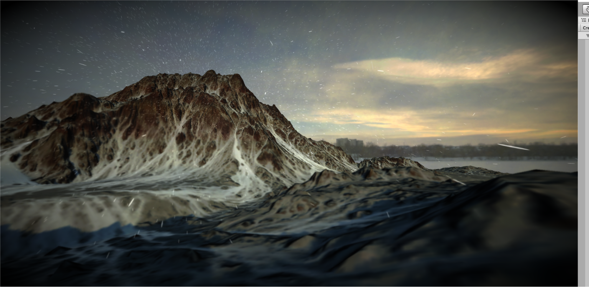
We should first go into our Initialization Context (Figure 01).
1. Change the Capacity to 50,000. This caps the amount of particles in the simulation to a maximum of 50,000, a decent amount for a snowstorm.
While we see an abundance of particles as a result, they are all concentrated in a small part of the screen. This can be addressed in the Set Velocity Random Block.
2. Uniformly increase the size of the values in the Set Velocity Block to at least ±10. This effectively increases the volume the particles can move around in, distributing them more evenly across your Scene and providing them with a random velocity (Figure 02).
Now, let’s traverse down to the bottom of our graph and look at Output Particle Quad Context.
The default particle resembles nothing like snow, so this will be the first thing we modify (Figure 03).
3. Select the radio button next to Main Texture field. In the explorer window, search for “Knob” and select the “Knob” Texture. Feel free to use your own texture if you have it, but “Knob” is good for its uniform appearance and soft outlines that will make the effect more visible against brighter backgrounds.
4. Right above that field, set the Blend Mode to Additive. This will make the snow appear brighter as the individual particles overlap each other, subsequently increasing visibility.
Currently, we have a stream of round particles flying directly toward the camera. This does not look very convincing, and while it may suffice in a 2D Scene, it (literally) falls flat in 3D. To correct this, we will make a change to the Orient Block.
5. In the Orient Block, change the Mode from ‘FaceCameraPlane’ to ‘AlongVelocity.’ This will make the snow particles face the direction that they are travelling. While it does not produce a pronounced effect now, it will in a later step (Figure 04).
Before exiting the Output Particle Quad Context, notice how large the particles are. The longer the snow particles live, the closer they get to the camera. We want the particles to appear larger the longer that they are alive, but the default value makes the snow take on more of the appearance of hail.
6. Go to the Set Size Over Life Block and double click on the curve next to Size (Figure 05).
The curve represents time (on the x-axis) and size (on the y-axis) on a normalized scale of 0 to 1. By default, the particles steadily grow until they disappear. We want to change this curve so that the particles continue to steadily grow, but are capped to a much smaller size.
7. At x = 1, adjust the y-coordinate to a value around 0.1 and 0.3 (Figure 06).
The snow will now appear a more realistic size. We can leave the other properties of this Context at its default. The Color/Alpha Over Life Block by default fades particles in when they spawn, and fades them out as they approach the end of their lifespan - which is the desired behavior.
3. Determining Spawn Rate
Currently, the particle system emits snow at a constant rate. In real-life, the amount of snow falls at a variable rate depending on the current intensity of the storm. As with Shader Graph, we can use time based Nodes to control the spawn rate, and subsequently the intensity of the storm over time.
8. Navigate just outside Spawn Context in the graph, press the Space key and search for “Periodic Total Time,” then select that Node type to create it (Figure 07).
This node has two inputs: Period and Range. The Period denotes how many seconds must pass before a value within the Range is selected. For example, if the Range is set to [0, 10] and the Period is set to 2, a new value between 0 and 10 will be selected every 2 seconds:
2s -> 4
4s -> 1
6s -> 10
As you can see, this will allow us to change the spawn rate of the system every few seconds.
Let’s create two variables to drive these values.
9. Navigate to the Blackboard and create two variables: a float and a Vector2. Name the variables “SpawnRate” and “SpawnRange” respectively (Figure 08).
10. Connect the “SpawnRate” to the Periodic Total Time Node’s Period input. Then connect the “SpawnRange” to the Periodic Total Time node’s Range input.
11. Adjust the “SpawnRate” and “SpawnRange” to your liking. It usually looks good to alternate the rate of snowfall by a large value (ie: between 100 and 20,000) every 10-30 seconds. Another Periodic Total Time node can drive the Period of this one if you wanted to vary the time interval for even more randomness.
12. Connect the output of this Node to the Rate Input of the Constant Spawn Rate Block (Figure 09).
You should now see the amount of particles in the system vary over time.
4. Simulating Motion & Scale with Vector Fields
While the basic behavior of the system is complete, the particles themselves still move outward in a straight line. We will modify the Update Context to make the particles move as if they were flowing along an air current.
13. In the Update Context, create a Vector Field Force Block. This Block provides a 3D vector field texture as an input by default. This 3D texture populates the velocity volume we defined earlier with an array of vectors in 3D space. Each vector propels particles in the direction that they are oriented in 3D space (Figure 10).
In this context, a vector field acts as a digital representation of an air current in 3D space. This can be best conceptualized by imagining the display of air currents on a weather forecast program.
14. To add more divergence to the vector field, add a Turbulence Block to the Update Context and increase its Intensity (Figure 11).
The last change we will make to our Update Block will dynamically change the size of the particles based on their speed to give them a streaky appearance more characteristic of snow.
15. Create a Set Scale by Speed Node and set the Channels property to XY since we are dealing with two dimensional particles in the XY plane (Figure 12).
Notice the Speed Range property of this Block. The X value denotes the minimum speed we will account for, and the Y value denotes the maximum speed that will be accounted for. Similar to the Set Size over Life Block, this Block maps this range to a value between 0 and 1. We want the X Scale of each particle to decrease and the Y scale of each particle to increase once it gets closer to the maximum speed.
16. Open the curve editor for Scale_x. As the speed is mapped to the x-axis of the curve, gradually decrease the y-coordinate to a value between 0 and 0.2 when x is at least 0.8 (Figure 13).
17. Now open the curve editor for Scale_y. Gradually increase the y-coordinate to a value between 1 and 1.5 when x is at least 0.8. We are exceeding the normalized space of 0 to 1 in this instance as we want the particle to stretch vertically beyond its circular shape once it reaches a certain speed (Figure 14).
The system is starting to look a lot more like snow!
5. Animating the Transform over Time
One last thing we can do is adjust the origin Transform of the particle system over time to make it appear more dynamic. We must go back to the Initialize Context and modify the values of the Set Position Block.
Before we begin, ensure that the Initialize Particle Block is operating in World Space.
18. In the upper right corner of the Initialize Particle Context, select the “Local” button. This will change the button to “World.” (Figure 15).
19. Add a Set Position Block and increase the value in the Y-axis so the system initializes outside the view of the Camera. This is moreso to create the illusion that the snow is coming from the sky (Figure 16).
20. Next, create a Sine Wave Node and connect its output to the Set Position Block’s X and Z inputs (Figure 17).
The goal here is to animate the X and Z position of the system along a sine wave. Though, the sine wave is currently only evaluating a fixed input, meaning it is not animating. We want the sine wave to evaluate a value that changes over time. There’s no better way to accomplish this than having the wave evaluate time itself.
21. Create a Total Time node and drag its output to the Sine Wave Node’s Input. You should now see the snow particle follow its origin as it moves across the Scene (Figure 18).
22. For extra flair, navigate back down to the Output Particle Quad Context and replace the Main Texture with the “Snowflake” Texture. Slower moving particles will now take on the appearance of snowflakes instead of a uniform circle (Figure 19).
6. Conclusion
This serves as an introduction to the foundations of VFX graph. Just with these simple building blocks you can already create dazzling effects. To explore more advanced topics such as GPU Events and Parameter Binds, please refer to this blog post by John O’Reilly: Creating explosive visuals with the Visual Effect Graph. There you can also download sample graphs which demonstrate these advanced effects and other concepts which will aid you in bringing your effects ideas to reality!