Use the UV Editor to unwrap UVs
Tutorial
intermediate
+10XP
30 mins
34
Unity Technologies
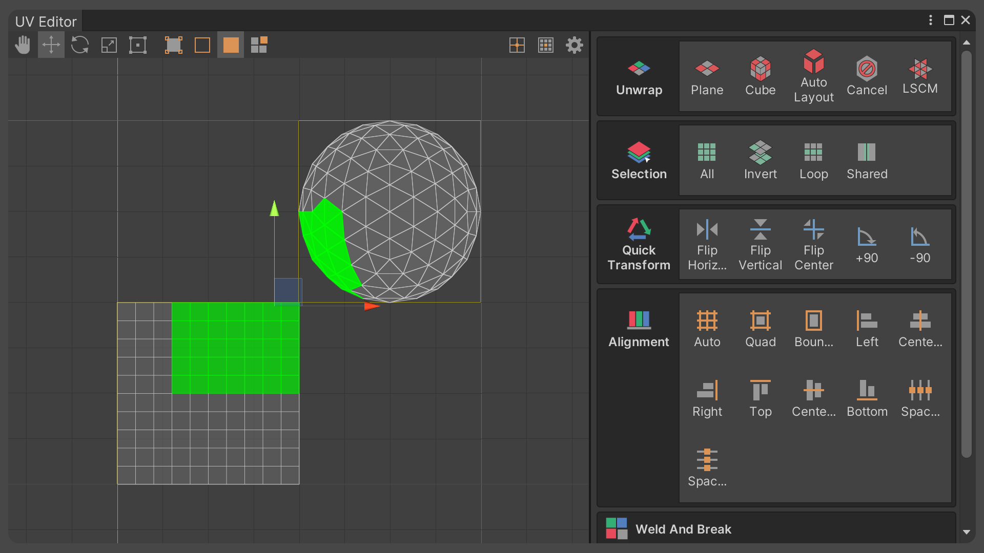
In this tutorial, you will learn how to use UModeler X’s UV Editor to map 2D images onto 3D models. This will allow you to accurately apply textures, which are 2D images, to 3D models.
Languages available:
1. Overview
UV is a texture coordinate in 2D form that corresponds to an object in 3D form. The UV Editor allows you to create and edit UV elements (UV Vertices, UV Edges, and UV Faces).
2. Before you begin
New to Unity?
If you’re new to Unity, welcome! The Unity Essentials learning pathway has been designed to help you get set up and ready to create in the Unity Editor. We recommend you complete this pathway before continuing with this UModeler X tutorial.
Update the Unity Hub
Before you begin to set up your Unity project, consider updating your Unity Hub to the latest release. If you are using an older version of the Hub, there may be differences between the guidance provided and your experience.
Review the Unity Editor basics
If you need to refresh your memory of the Unity Editor basics, you can take a moment to review Explore the Unity Editor at any time.
3. Understanding texture coordinates and UVmapping
Why create texture coordinates?
The reason for creating texture coordinates is to properly represent the complex surfaces and bends of a 3D model in 2D space. Doing this allows you to accurately apply textures, which are 2D images, to 3D models.
Unfolding texture coordinates is similar to unfolding a shipping box to make it flat.

Although the box is a 3D shape, you can easily make it into a 2D shape by unfolding it to make it flat. If you want to put a label or sticker on each side of a parcel box, you need to unfold the box so that each side is flat.
This will ensure that the label or sticker is applied correctly to the box and will look natural.

Because the surface of a 3D model is made up of various curves and shapes, the process of representing it in 2D space can cause distortion.
Unwrapping a 3D model into 2D texture coordinates should focus on minimizing distortion to ensure the texture appears natural on the model's surface.
Mapping
Mapping is the process of connecting or transforming information from one data set or space to another. Mapping is used in many different forms in many different fields.
In 3D graphics, Mapping primarily refers to texture mapping, which is the process of gluing a 2D image (texture) to the surface of a 3D model. This allows you to represent a 2D image on a 3D model.
To make mapping a little easier to understand, let's use the example of a poster on a wall.
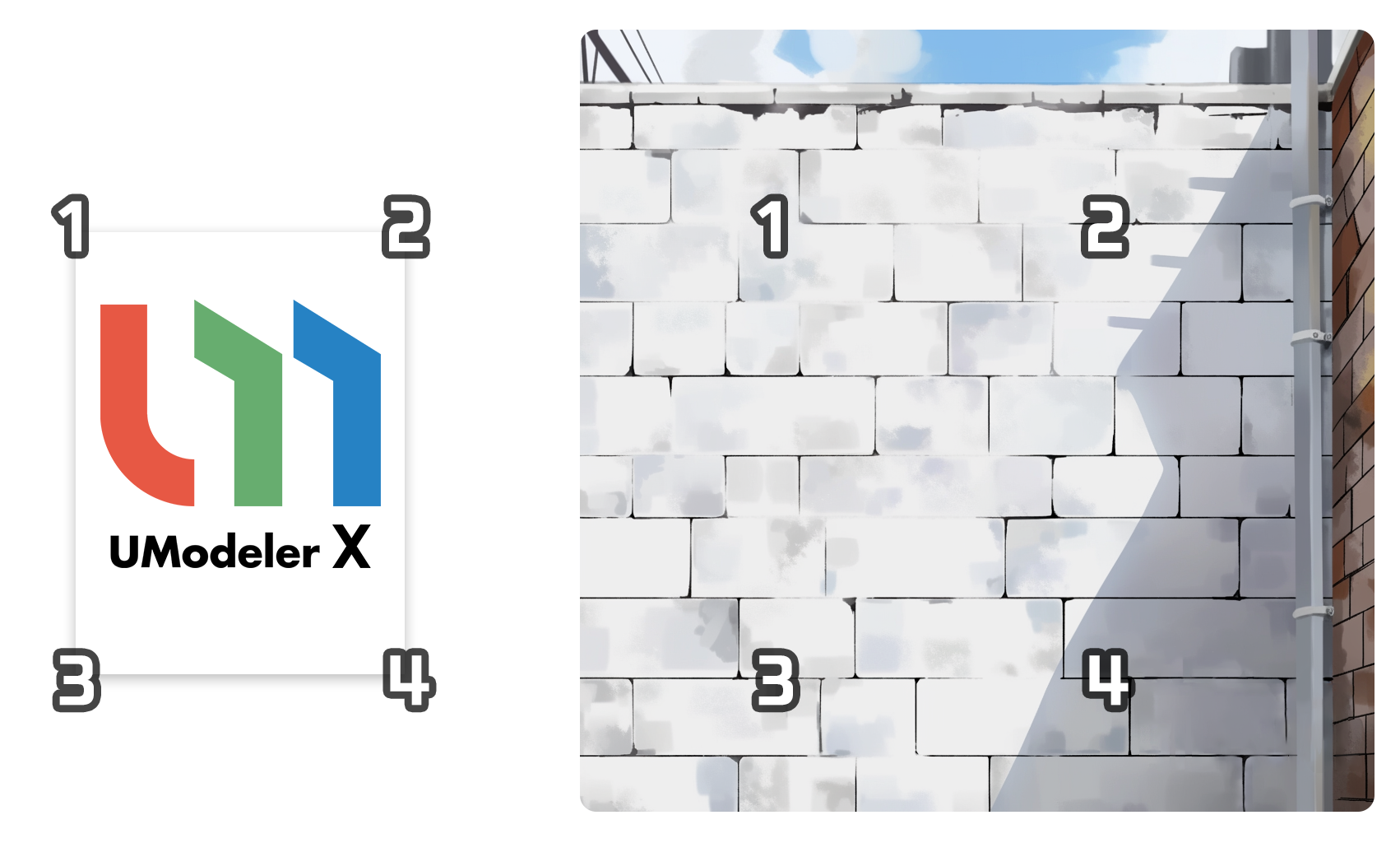
The idea behind mapping is that a poster (2D image) is attached to a wall (3D space), adding a new image to the wall.
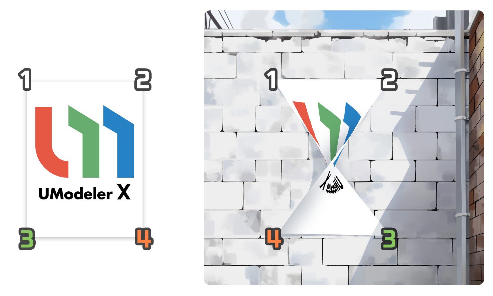
However, in this case, in order for the poster to be correctly attached to the wall, the corners of the poster need to exactly match a specific location on the wall.
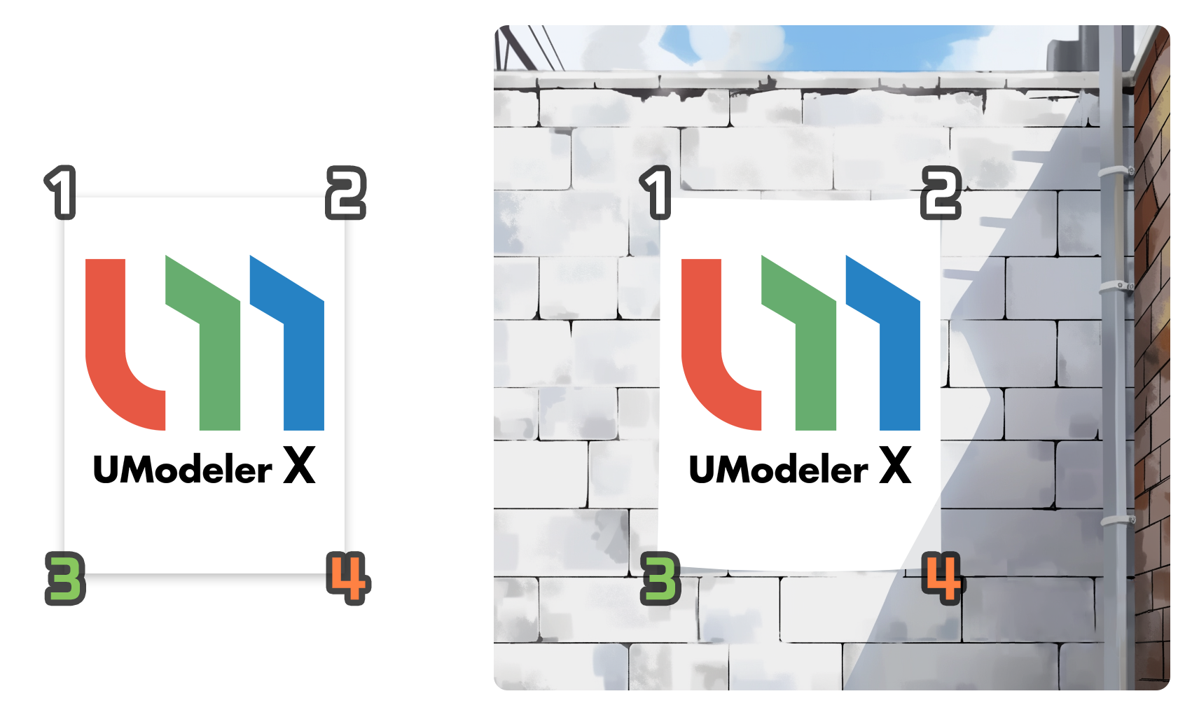
This process of fitting a 2D image into 3D space is what we call texture mapping.
Texture coordinates and UV mapping
Texture coordinates are coordinates used to map textures to a 3D model. The most common method of texture coordinates is UV mapping. UV mapping uses the texture's horizontal (U) and vertical (V) coordinates to map the texture to the 3D model. To understand texture coordinates and UV mapping, you first need to know something about 3D modeling and texturing.
3D modeling is the three-dimensional representation of real-world objects on a computer, and texturing is the process of applying colors, materials, etc. to the surface of these 3D models. Among the texture coordinates used for UV mapping, UV coordinates are coordinates in 2D form that are assigned to each vertex of a 3D model. The UV coordinates use two axes, U and V, to represent the horizontal and vertical position of the texture.
The UV coordinates should be set to match the coordinates of the texture image. By doing so, there is a one-to-one mapping between the vertices in the 3D model and the pixels in the texture image, which ensures that the texture is accurately applied to the surface of the 3D model.
4. Launch the UV Editor
As a first step to begin the texture mapping process, you will need to launch UModeler X's UV Editor in order to stretch out your UVs. The UV Editor allows you to create and edit UV elements (UV Vertices, UV Edges, and UV Faces).
You can launch the UV Editor in the following ways:
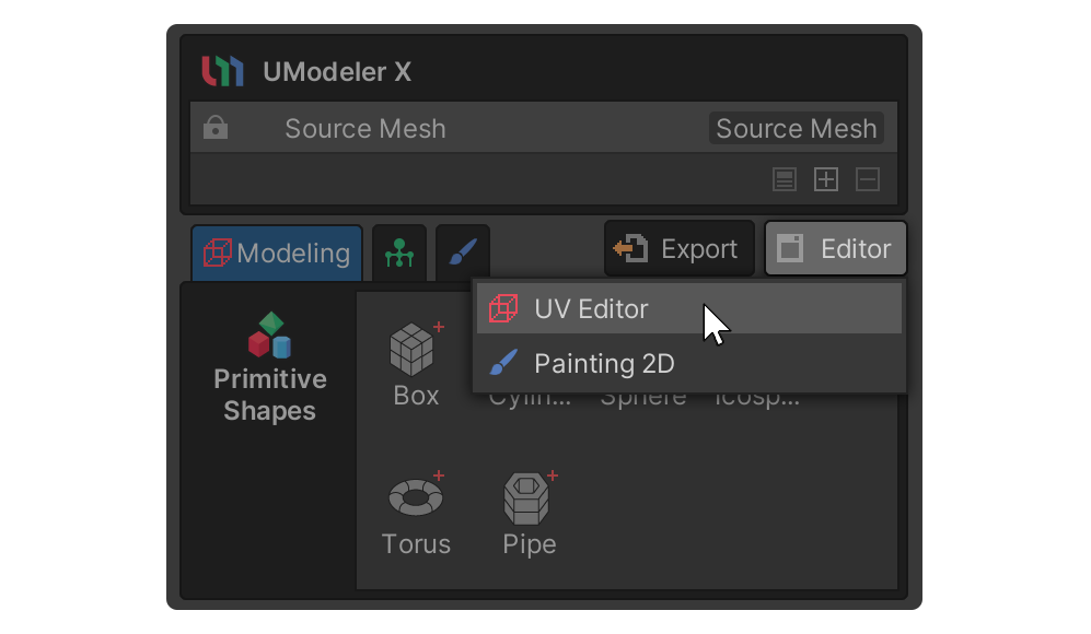
Source Mesh > UV Editor tool
1. Select the desired 3D object (Source Mesh).
2. Select the Editor button.
3. Select the UV Editor tool from the dropdown menu.
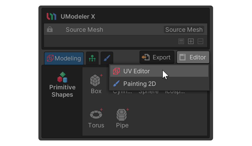
The UV Editor will be activated and you will see several UV elements (UV Vertex, UV Edge, UV Face).
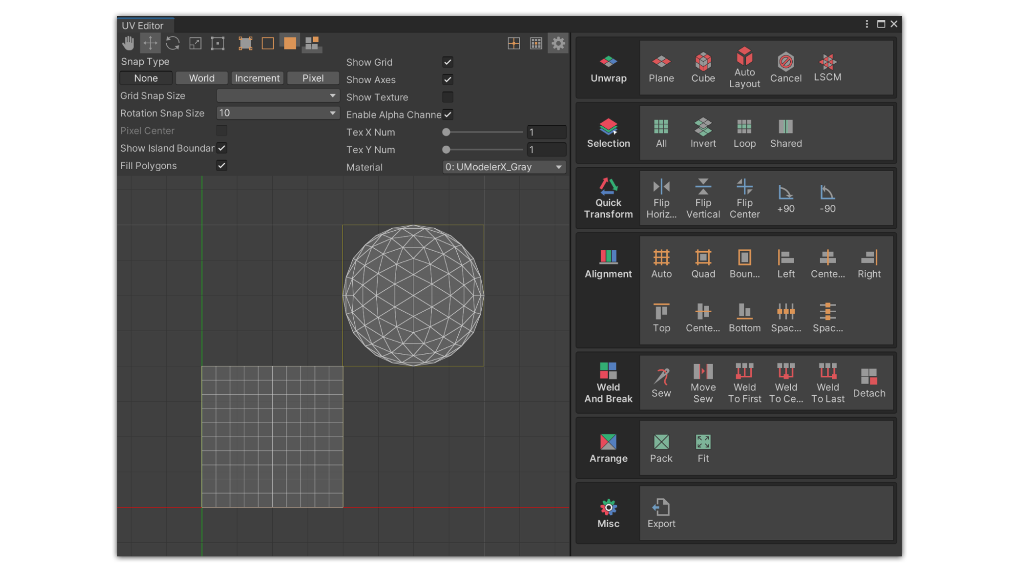
You can dock the UV Editor window tab next to the Scene view by dragging it.
Select object > Select Open UV Editor Tab
1. Select a UModeler X object.
2. Select the UV Editor tab.

Note: If a UModeler X object is not selected, the UV Editor will not be activated.
5. UV Editor interface
The UV Editor is a standalone editor, separate from the UModeler X component, that allows for fine-grained editing of UVs. At first, you may think the UV Editor is complicated because it feels different from the other modes in UModeler X, but once you understand the UV Editor's interface and how it works, you'll be able to utilize it with ease.
UV Editor and Scene view
When using the UV Editor, it is recommended that you use it in conjunction with the Scene view. By utilizing the space in the UV Editor and the 3D space in the Scene View, you can unwrap and edit UVs more efficiently. Below are some of the benefits of using the UV Editor and Scene view together, as well as a description of UV elements that are slightly different from traditional elements.
Utilizing space
When using UV Editor, the space is divided into two main parts. These are the Scene view and the UV Editor workspace. In order to generate good UV coordinates, you need to edit UVs while viewing different parts of the model. The Scene view is where you view the various parts of your model, and the UV Editor is where you actually edit the UVs.
UV elements
Elements selected in each area can be viewed in the other area, but elements in the model and elements in UV Editor are two different things. In UModeler X, the vertices, edges, and faces that appear in the UV Editor are all referred to as UV elements, i.e., UV vertices, UV edges, and UV faces.
Understanding the UV Editor interface
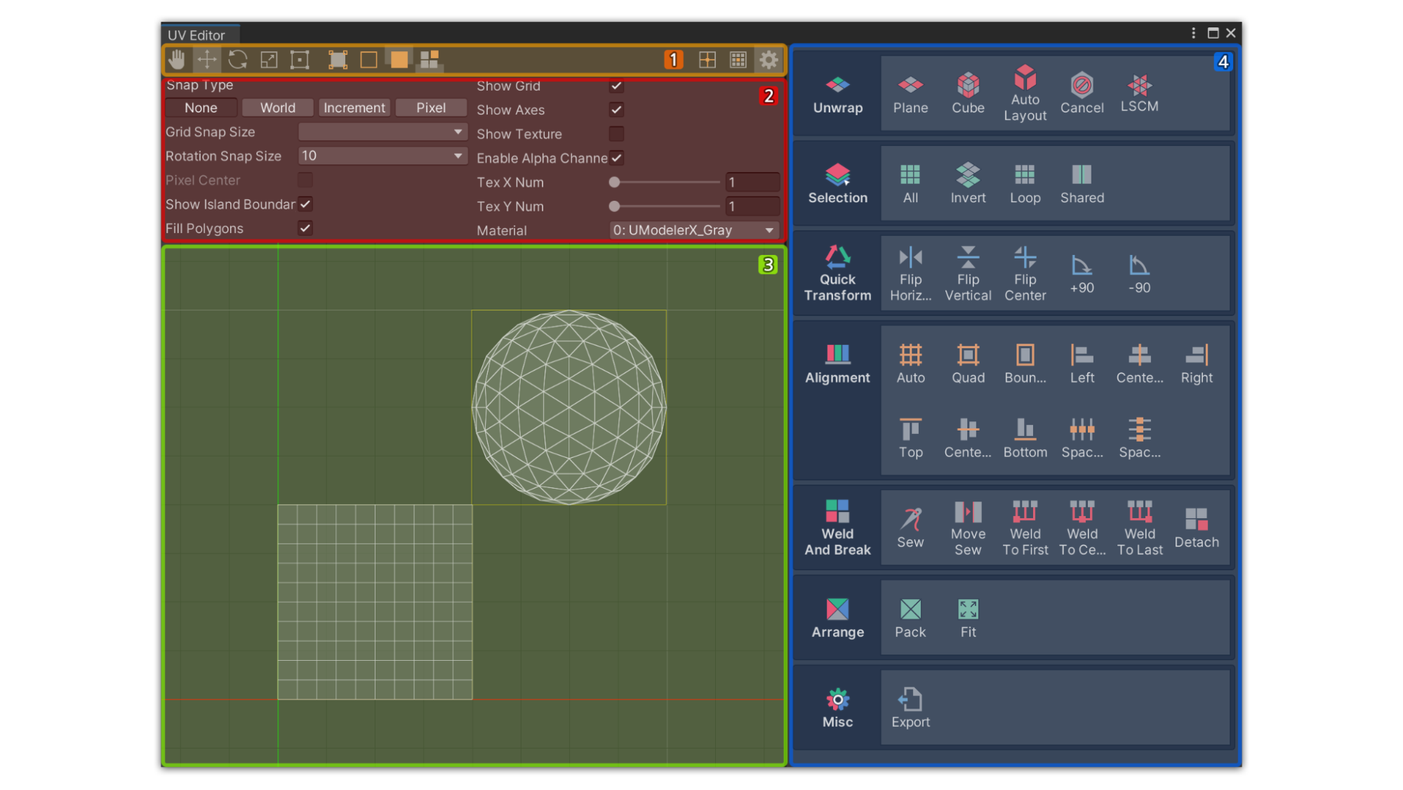
The UV Editor interface consists of four main areas:
- Toolbar: This is where the screen pan, transform gizmo, UV element selection tools, and cursor are listed, in that order
- Settings panel: If you select the Settings button, you will see the Settings panel, which is where you can change the settings of the UV Editor. This is where you can adjust the operation settings and visuals for the UV Editor
- The Workspace: This is where you can directly edit UV elements, view grids, textures, and UV elements, and select or manipulate UVs
- UV Tool panel: A collection of tools for selecting, expanding, and placing UV elements. The tools are organized into groups so you can use UV Editor effectively by selecting tools according to the group's characteristics.
6. Select Faces and Unwrap them
Below is a simple process for unwrapping a sphere using the Cube Unwrap tool in the UV Editor, which allows you to map a texture and add more detail to the sphere's surface.
If you follow along, you should be able to get a basic feel for the sequence of UV unwraps. To unwrap a 3D model in 2D, follow these instructions:
1. Select a UModeler X object in Unity's Scene view.
2. Select all faces of your model to unwrap the entire model into 2D.
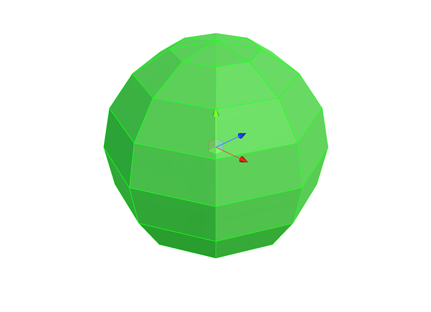
3. Open UModeler X's UV Editor.
4. Select the Cube tool inside the Unwrap group.

5. You can find a property and a button related to the Cube tool in the Unwrap group, located on the right side of the UV Editor window.

6. Enable Individual property to unwrap each face individually. If disabled, the faces will be unwrapped together.
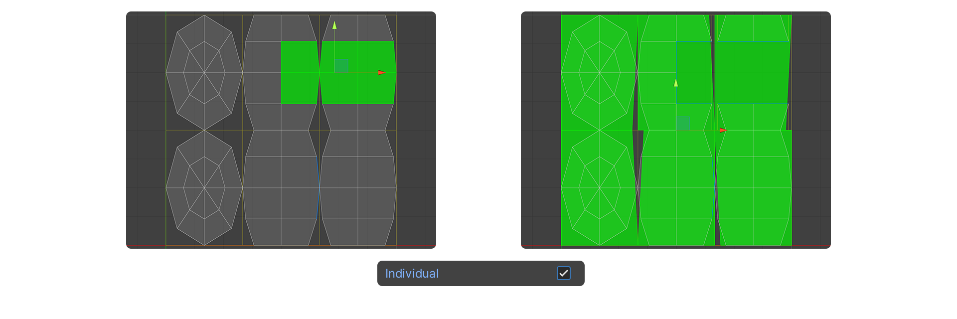
7. Select the Unwrap button after finishing the settings.

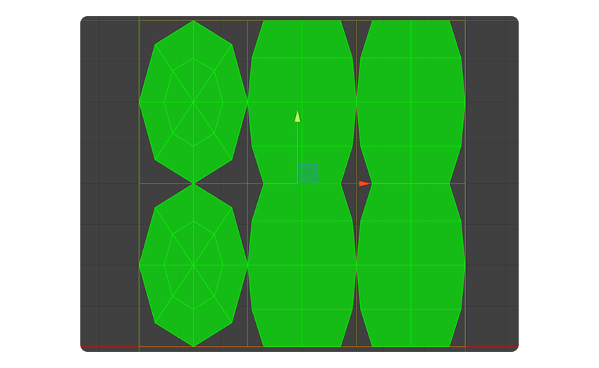
Congratulations! You now have the ability to utilize UModeler X's UV Editor to perform basic UV unwraps. So far, we've covered relatively simple unwrap operations. Next, we will explore more complex and natural UV editing techniques using the LSCM tool.
Using the LSCM tool
The Least Squares Conformal Maps (LSCM) tool is a UV editing tool that uses the LSCM algorithm to generate natural UV coordinates. The LSCM algorithm calculates the least squares distance, a concept introduced in this paper, to produce the optimal UV.
To unwrap a model while preserving its 3D shape as much as possible using the LSCM tool, follow these instructions:
1. Select an edge of the model you wish to edit and set a UV Seam with the Mark UV Seam tool in the Surface group.
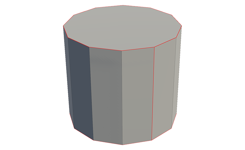
2. Select the LSCM tool from the Unwrap group in UV Editor.

When you select the LSCM tool, it will generate a natural UV based on the UV Seam you set.
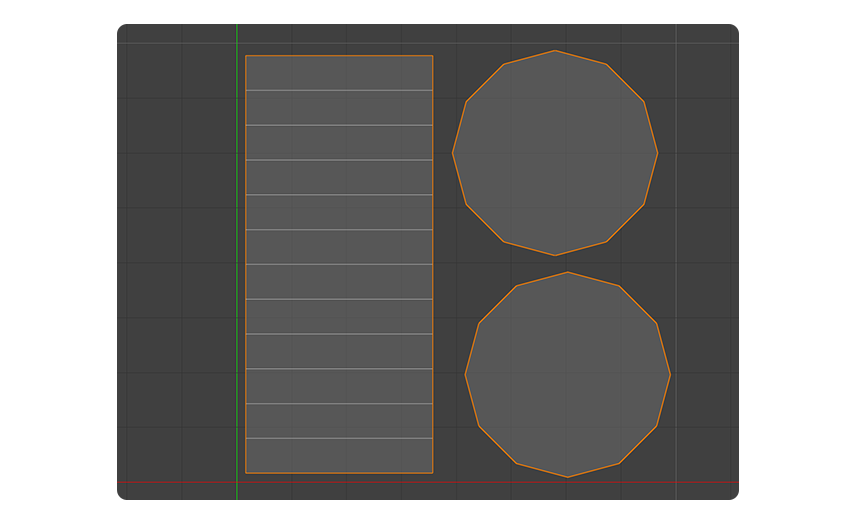
Note: If you want to remove the UV Seam, you can use the Unmark UV Seam tool.
7. Place unwrapped UV elements in texture space
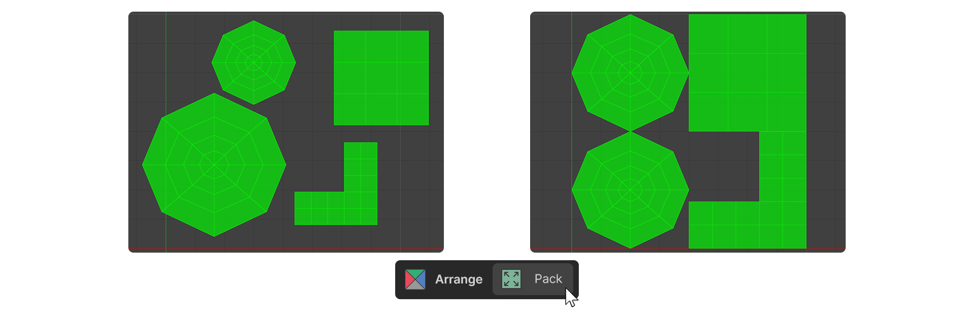
Once you have unwrapped all of your UVs, you need to place them in 2D texture space. Keep the following considerations in mind while moving, rotating, and scaling each UV to ensure that the texture appears with minimal distortion and is correctly aligned:
- Locate and orientate each UV element to make texturing easier
- Size UV elements based on importance
- Zone UV elements based on material
If you have a pre-made texture, you can simply place each unwrapped UV in the appropriate location in the texture image. To place UVs, follow these instructions:
1. Select the UV elements you want to edit.
2. In the Arrange group, select either the Pack or Fit tool.

The Pack tool places UVs in texture space without overlapping. The Fit tool places UVs to fit in the texture space while maintaining the distance and size between the selected UVs.
3. If the placement does not work out the way you want, click and drag the UV elements to place them directly where you want them.
During the UV placement process, it is important to make sure that your UVs do not overlap each other. This is because if UVs overlap, the same texture image will be displayed on the faces of the model corresponding to the overlapping UVs.
Note: Overlapping is not always a problem, and sometimes you can intentionally overlap UVs to utilize texture space efficiently. You can also use this method to create different visual effects. In these cases, overlapping UVs can actually be an advantage.
8. Assign a texture and observe how the model appears wrapped in it
Finally, you can apply your texture to the desired faces of the model by using the Material tool in Modeling mode. The texture will be applied on the faces according to the UV coordinates you've set.
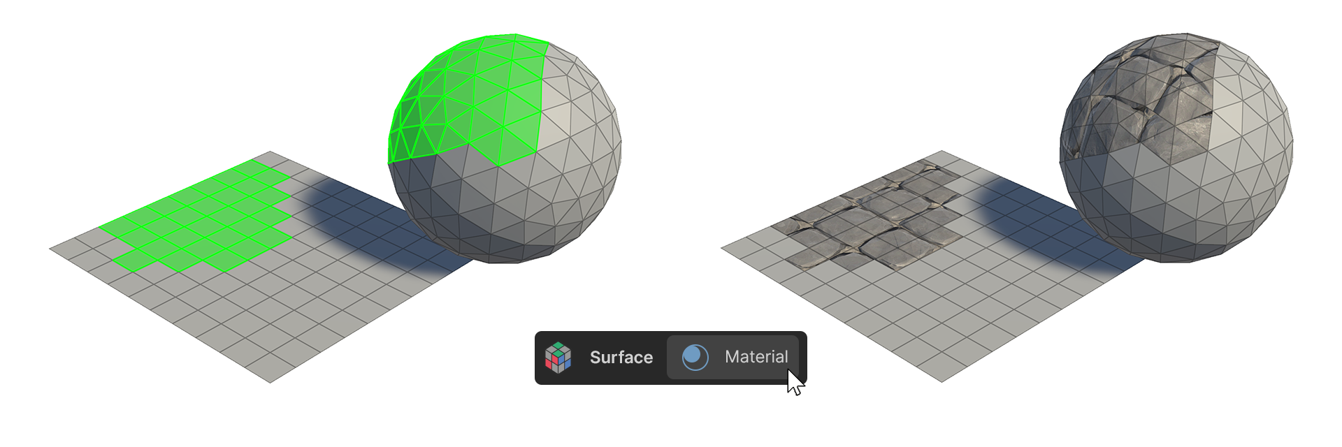
If you need to make further edits to the UV, you can do so with the texture already applied, which will allow you to edit the UV with visual feedback. This way, you can see how the texture changes with the UV in real time and edit the UV more accurately.
9. Next steps
Great job! You're now adept at UV unwrapping. In the next tutorial, you’ll bring your models to life with animation in Rigging mode.