Enhance your prototype with ProBuilder
Tutorial
·
Beginner
·
+10XP
·
45 mins
·
(74)
Unity Technologies

ProBuilder is a package that you can use to build, edit and texture custom geometry (3D shapes) in Unity. You can use it to create all sorts of objects in your environment that go beyond combinations of primitives.
By the end of this tutorial, you'll be able to:
- Explain how ProBuilder can support prototype development.
- Create meshes using Probuilder.
- Configure geometry to make basic scenery for a prototype.
- Set a Collider for a mesh.
- Set a mesh as a trigger.
Languages available:
1. Overview
There’s a tool available in Unity to help you enhance your prototype environment without creating models from scratch: ProBuilder!
ProBuilder is a package that you can use to build, edit and texture custom geometry (3D shapes) in Unity. You can use it to create all sorts of objects in your environment that go beyond combinations of primitives.
Want to create a series of mysterious monuments for a forest walking simulator or produce a city to become lost in? You can create either placeholders or the objects themselves (depending on the polish and stylistic approach you are taking) with ProBuilder.
Note: This tutorial is a starting point to support your prototyping needs rather than a comprehensive overview of ProBuilder.
2. Set up ProBuilder
To set up ProBuilder:
1. Install the ProBuilder package for your project.
2. In the main menu, go to Tools > ProBuilder. Here you’ll find all the options for working with ProBuilder.
3. The options in this window are presented as text by default. If your window is in Icon Mode, switch to Text Mode by selecting More (⋮) and then Use Text Mode.
3. Create a cube
You’re going to use ProBuilder to model geometry directly in the Unity Editor. Start by creating a cube:
1. In the Project window, go to Assets > CreativeCore_Prototyping > Scenes and create a new scene.
2. Open your new scene.
3. Go to Tools > ProBuilder > Editors > Create Shape > Cube.
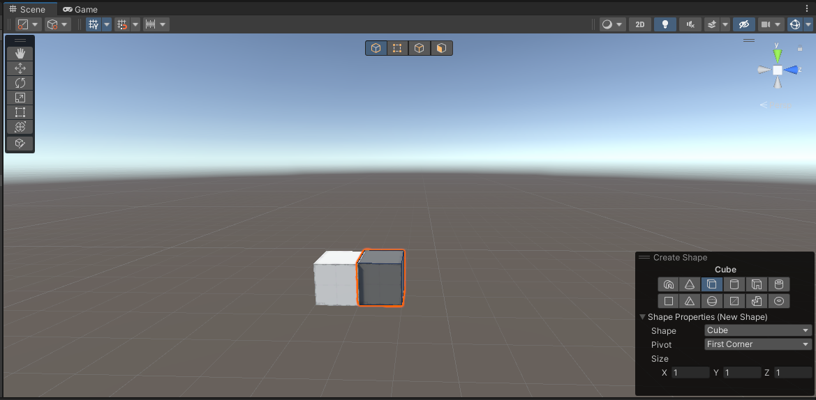
4. In the Shape Tool window, select the shape icon. Alternatively, you can expand the Shape Properties (New Shape) foldout, then set Shape to Cube.
5. Click and drag your cursor in the Scene view to set the length and width of the cube. When you release the selection, move your cursor and click again to set the height. You’ll notice that a new GameObject for the cube has appeared in the Hierarchy.
Note: You can create a second cube using the last dimensions that you set by holding Shift and then double-clicking in the Scene view when the preview cube is in your desired location.
You can now close the Shape Tool window and this preview will disappear.
4. Create a cube using the alternative method
Next, you need to create a second cube. You’ll use the cubes for different purposes, so leave your first cube in the scene.
Use this alternative method to create the cube:
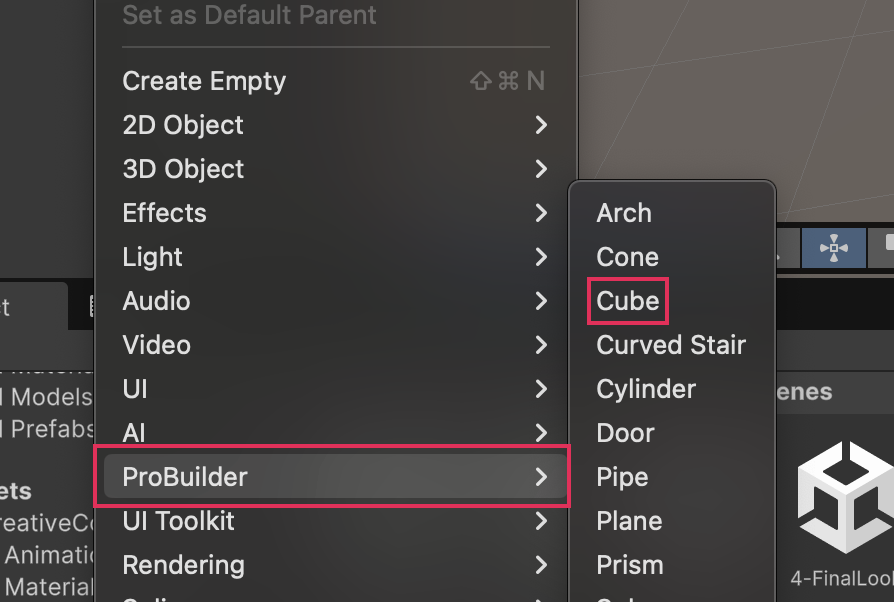
1. In the Hierarchy, right-click and select ProBuilder > Cube.
2. Select the new cube GameObject that you have just created. If you want to, you can give it a distinct name.
3. In the Scene view, move your second cube so that it is spaced apart from the first cube you created. This will make it easier to work on them individually
4. Select one of your cubes. In the Inspector window, choose Edit Shape to edit the cube.
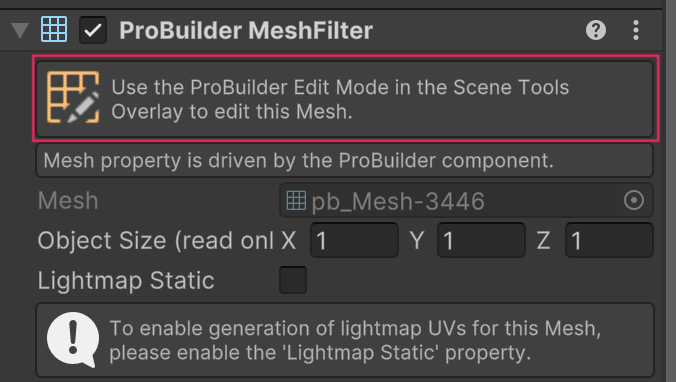
You’re going to be editing your ProBuilder GameObjects, and to do this you need to be in ProBuilder Edit mode that can be accessed in Scene Tools.
Note: If you ever need to find ProBuilder options again, go to Tools > ProBuilder.
5. Review the ProBuilder edit modes
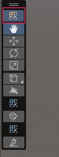
While ProBuilder is active in your Scene view, a toolbar should appear at the top of the Scene View If it does not appear, it can be activated manually by clicking on the Probuilder tool icon in your Scene view toolbar.

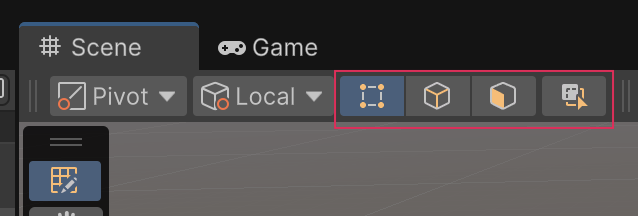
Each button of the toolbar changes what you are selecting in the Scene view.
Try the different selection modes out now:
1. In the Scene view, click on the cube to enable object edit mode.
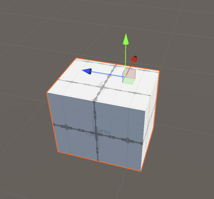
2. Left-click on your cube and then move, rotate, and rescale it. When you are finished, use Ctrl+Z (Windows) or Cmd+Z (macOS) to undo your changes.
3. Select Vertex Selection (second icon). You can use the vertex edit mode to work with vertices — the points where two or more angles meet. Left-click on one of the corners of your cube.
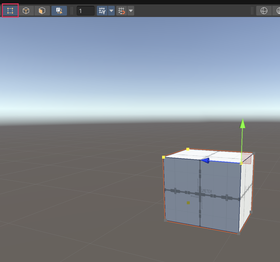
4. Move the vertex you have selected and see how you can change your cube in different ways. When you are finished, use Ctrl/Cmd + Z to undo your changes.
5. Select the Edge Selection tool. You can use the edge edit mode to work with edges, which consist of two vertices. Left-click on one of the edges of your cube.
6. Move, rotate, or scale the edge you have selected and see how you can change your cube in different ways. When you are finished, use Ctrl/Cmd + Z to undo your changes.
7. Enable Face Selection. You can use the face edit mode to work with whole faces of the mesh. Left-click on one of the faces of your cube.
8. Move, rotate, or rescale the face you have selected. When you are finished, use Ctrl/Cmd + Z to undo your changes.
6. Create a wall with your cube
Now that you know your way around the ProBuilder Edit modes, you’re ready to get started with creating a wall. Start by reshaping your cube:
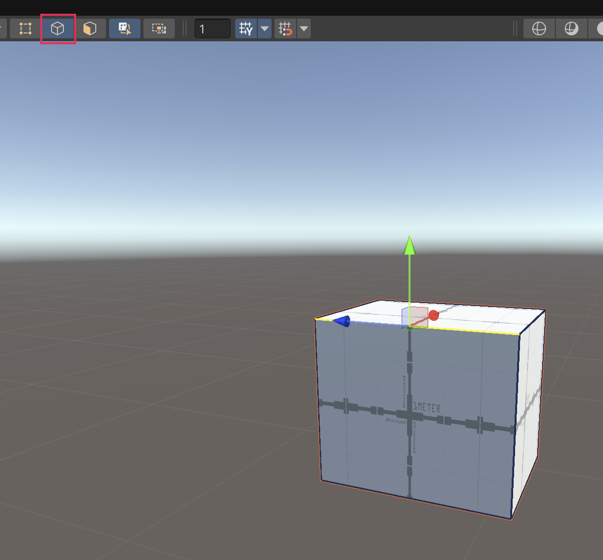
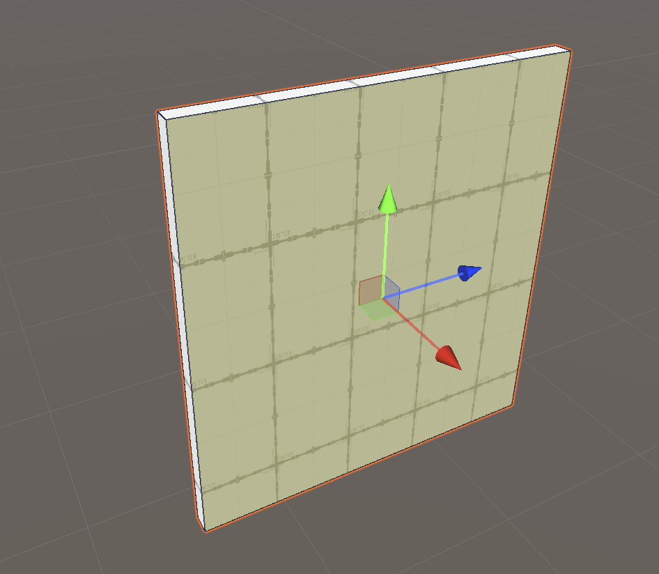
1. In the Scene view, select the Face Selection tool.
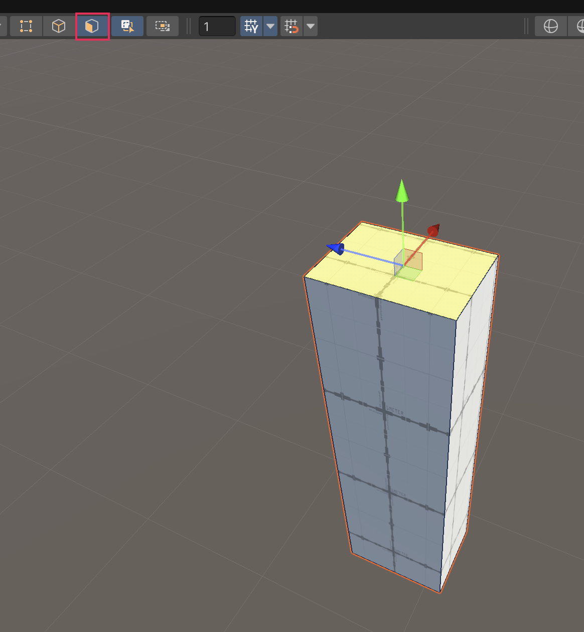
2. Select the top face of one of your cubes, then move the selected face to increase the height of the mesh.
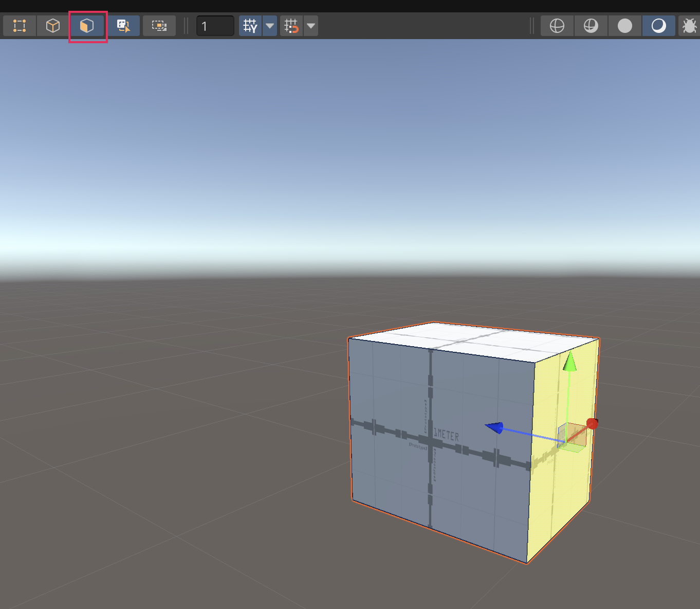
3. Select the side face of the cube, then move the selected face to increase the width of the mesh.
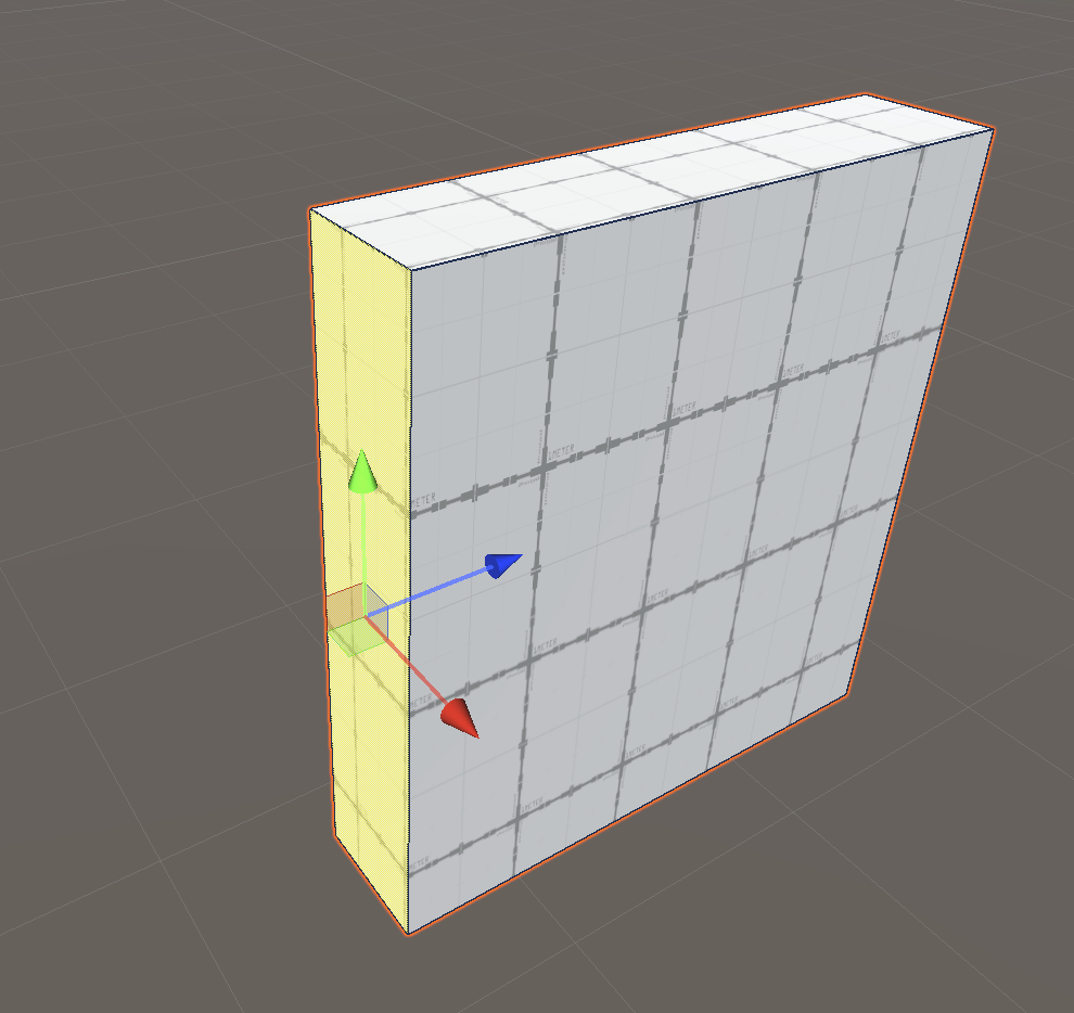
4. Select the front face of the cube, then move the selected face to decrease the depth of the mesh.
5. Repeat this process to create a second wall with your second cube.
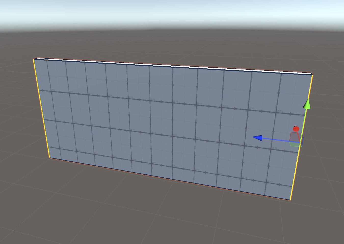
Once you’re finished, you should have two separate walls in your scene. Keep the walls apart and choose one to work on in the next step. You’ll return to editing the second wall later.
7. Extrude edges and faces to make a door
ProBuilder offers multiple tools to model your mesh. These appear in the ProBuilder window as you select parts of your object. The tools at your disposal will change dynamically based on the type of selection (object, vertex, edge, or face) you currently have enabled. Let’s start with one of the most important tools: extrusion.
To create a face on your wall that is the size of a door:
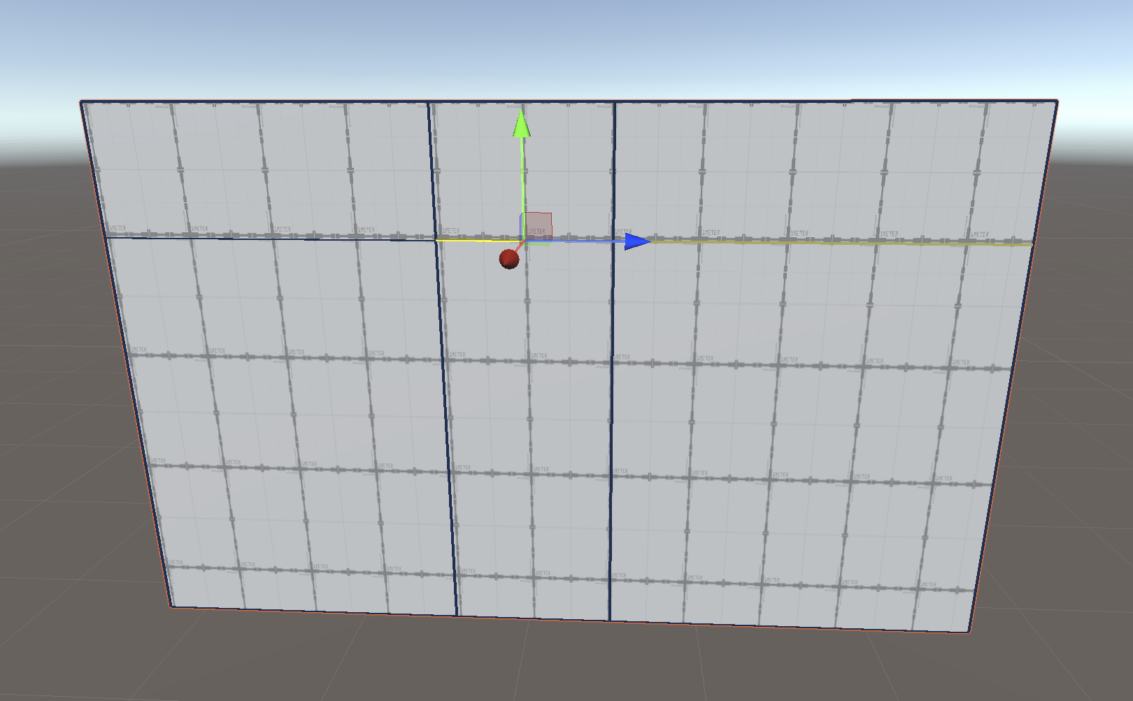
1. In the Scene view, with Face Selection enabled, select the top face of your wall.
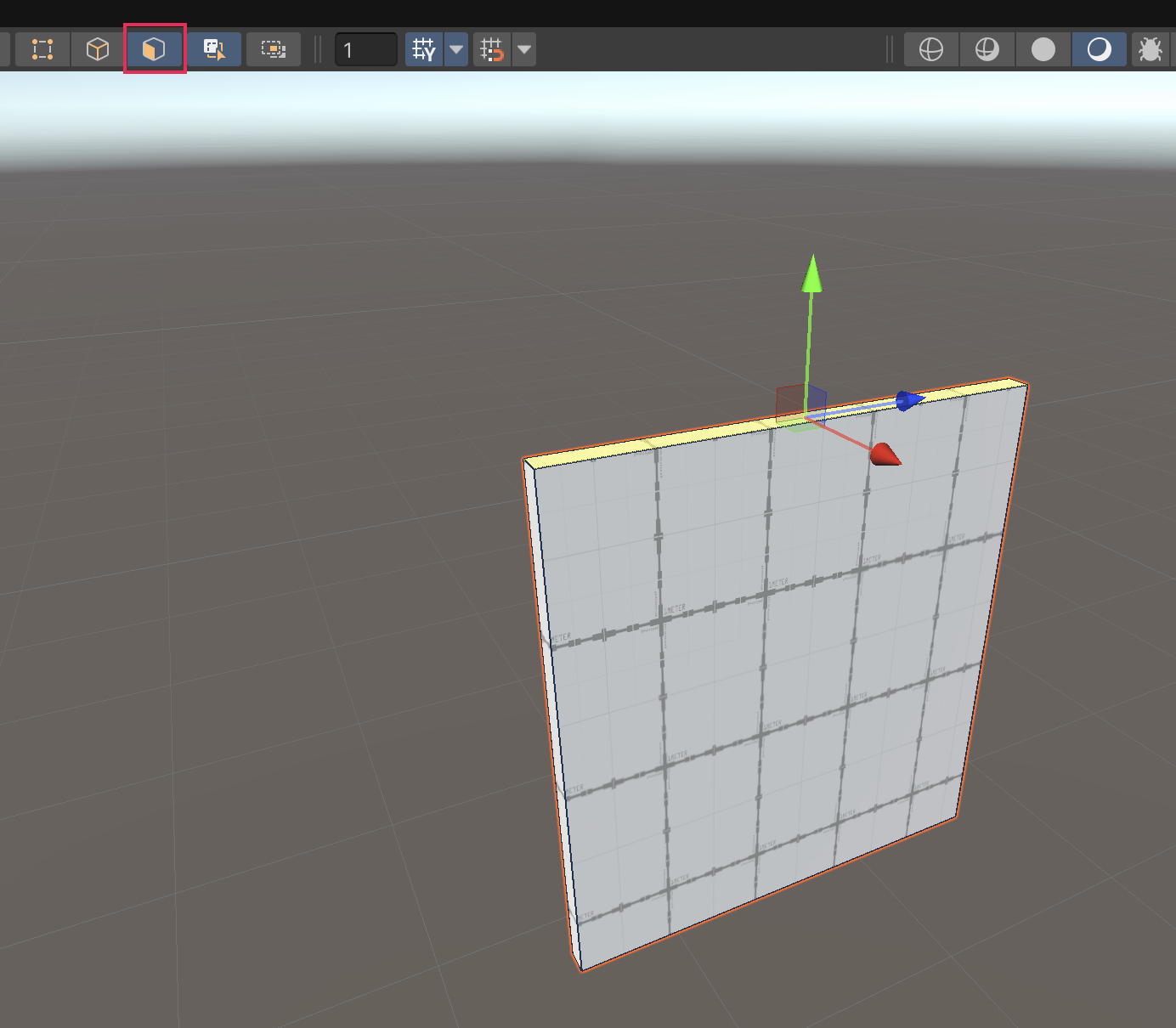
2. Hold Shift while moving the selected face to extrude it. This extruded segment marks the height of the wall above the door.
3. Hold Shift and left-click once on each of the two faces on the left side of the wall to multi-select them.
4. Continue to hold Shift while moving the selected faces to extrude them to the width that you want to give the door. These extruded segments will become the door and the wall section above it.
5. With the same two faces still selected, hold Shift and extrude the faces again to continue the wall after the placement of the door.
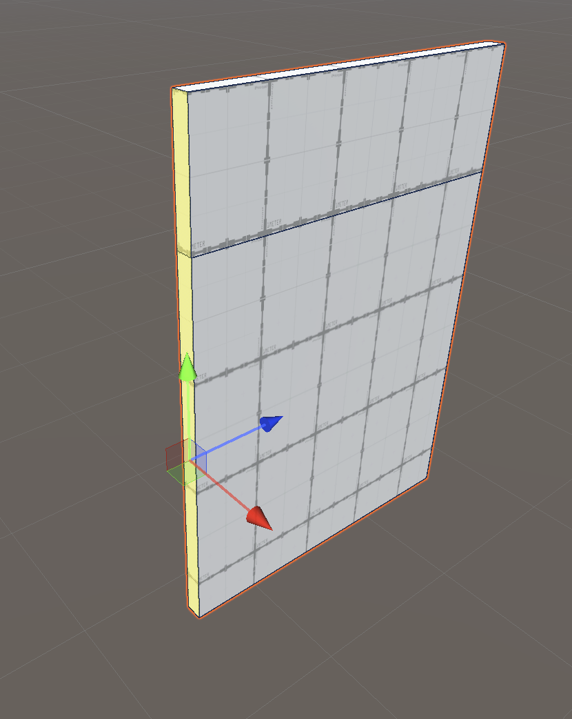
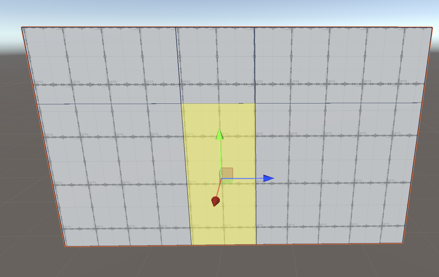
Now you’ve finished extruding the wall — the face highlighted in the image below is the face that will become the hole for your door:
Don’t worry if this face is not quite the shape you want right now.
8. Adjust the shape of the door
Now that you have the right amount of faces needed to make a door, you’ll need to adjust the size of the face that will become the doorway.
To select and move edges:
1. In the Scene view, enable Edge Selection.
2. Select the right edge of the face where your door will be.
3. Select Tools > ProBuilder > Selection > Select Loop. This will select all of the adjacent edges that ‘loop’ around the model.
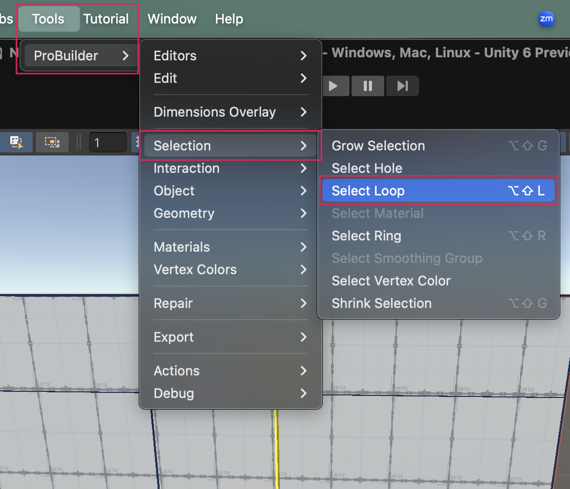
Tip: The Select Ring tool will select edges in a ring the other way around the model. Remember these tools to help you quickly select the edges you need!
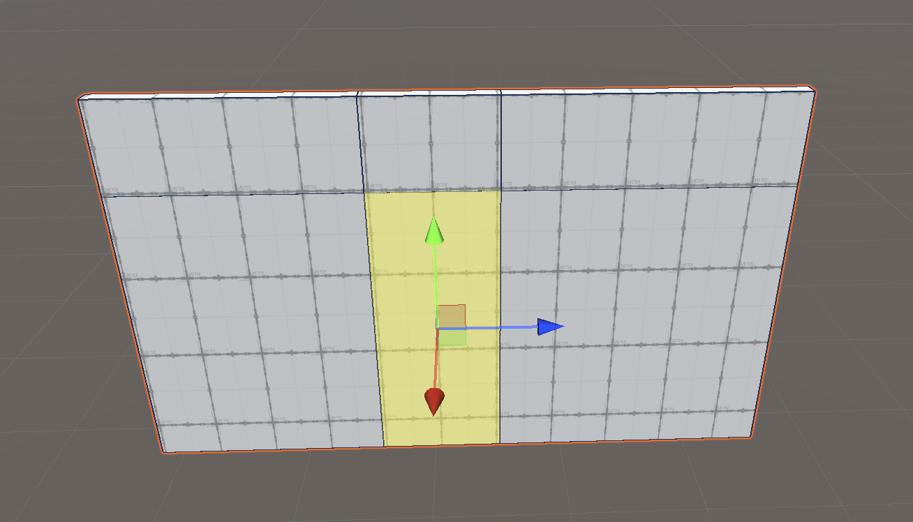
4. In the Scene view, with your vertical loop of edges selected, move the edges along your wall to the desired width.
5. Next, select the top edge of where your door will be.
6. In the ProBuilder window, select Select Edge Loop, then move the edges up or down your wall to the desired height.
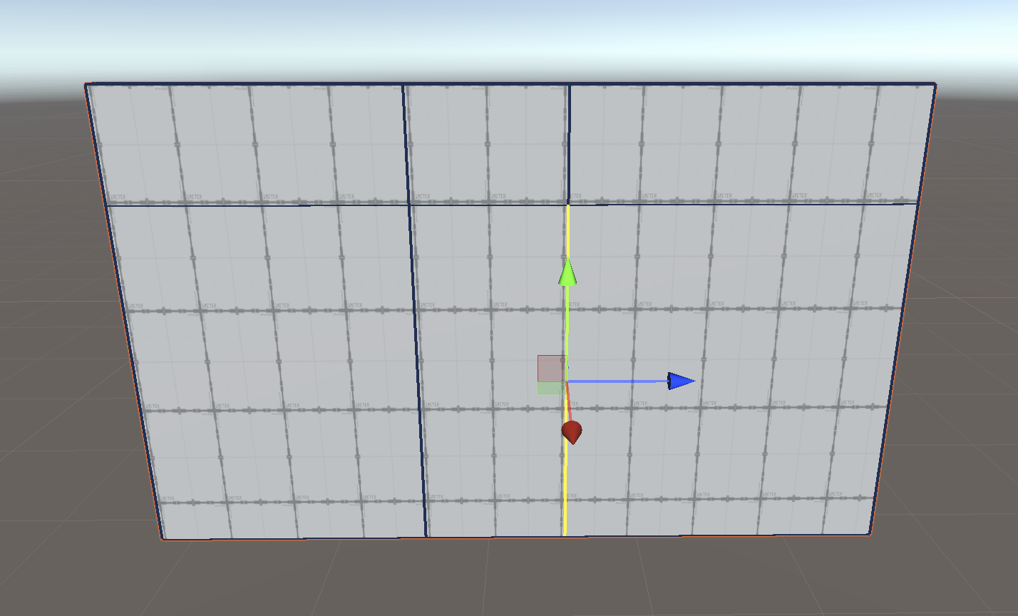
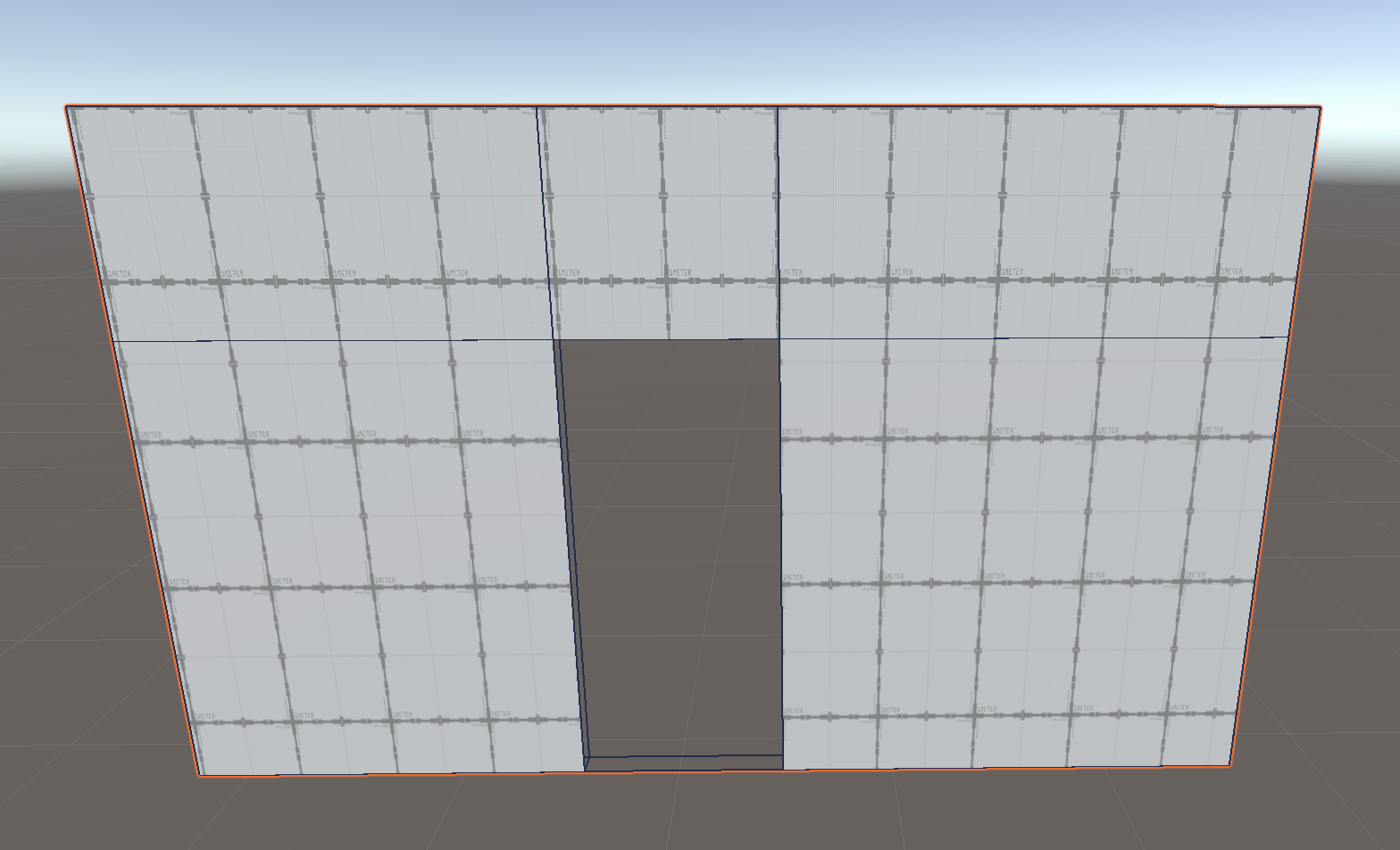
Now you should have a door that’s the shape and size you want!
9. Clear a hole for the door
Now that your faces are the right shape and size, all that’s left to do is clear those faces and create the door:
1. In the Scene view, enable Face Selection.
2. Select the face for your door.
3. Use Backspace (Windows) or Delete (macOS) to clear this face.
Note: It looks like you already have a hole, but that’s because faces are only visible from one side.
4. In the Scene view, move your Camera to look at the other side of the wall. You will see that the opposing face is still there. Repeat the previous steps to remove this face and the face at the bottom of the door.
10. Bridge the gaps to solidify the frame
You are now really close to having a door, but there are currently holes in the mesh where you have removed the faces — the inside of the wall mesh is currently exposed through those gaps. Luckily, ProBuilder has a function that you can use to bridge the empty space between edges.
Use the bridge function to close the gaps:
1. In the Scene view, enable Edge Selection.
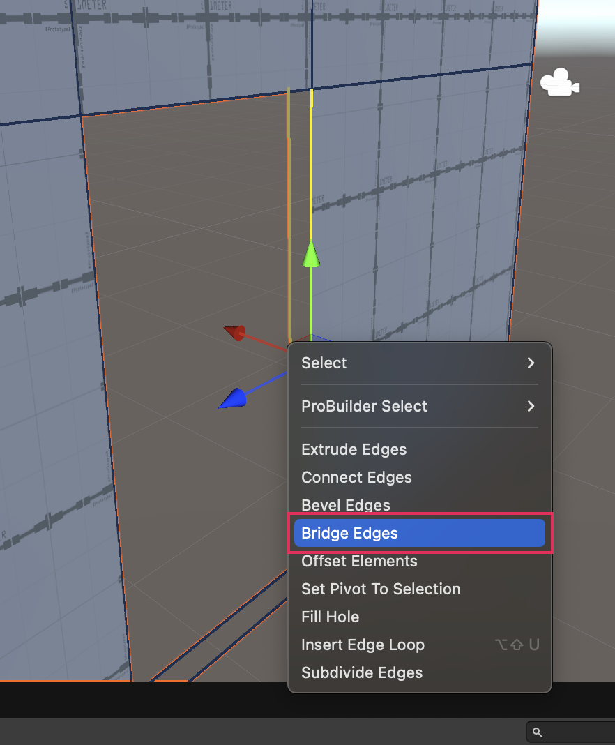
2. Shift + left-click to multi-select two parallel edges on the side of the door that you would like to bridge.
3. Right click to bring up the context menu and select Bridge Edges.
4. In the Scene view, multi-select two more parallel edges on your door.
5. In the ProBuilder window, select Bridge Edges.
6. Repeat the previous steps for the final side of your door, to close the gap there as well.
You should now have a door in your wall that is the right size and shape with no gaps!
11. Create a door in a pre-existing wall
Extruding is a good method to make a door, but it does require planning ahead to extrude at the right place. What happens if you want to create a door later, when after some testing you realize an existing wall would benefit from a new door or a new window? In that case, you need to insert new edges in a pre-existing face.
Return to that leftover wall from earlier in the tutorial. For this method, you need to recreate the edge configuration that you had in the previous example without using the extrude tool. You can do this by adding edge loops.
To create a door in a pre-existing wall:
1. In the Scene view, enable Edge Selection.
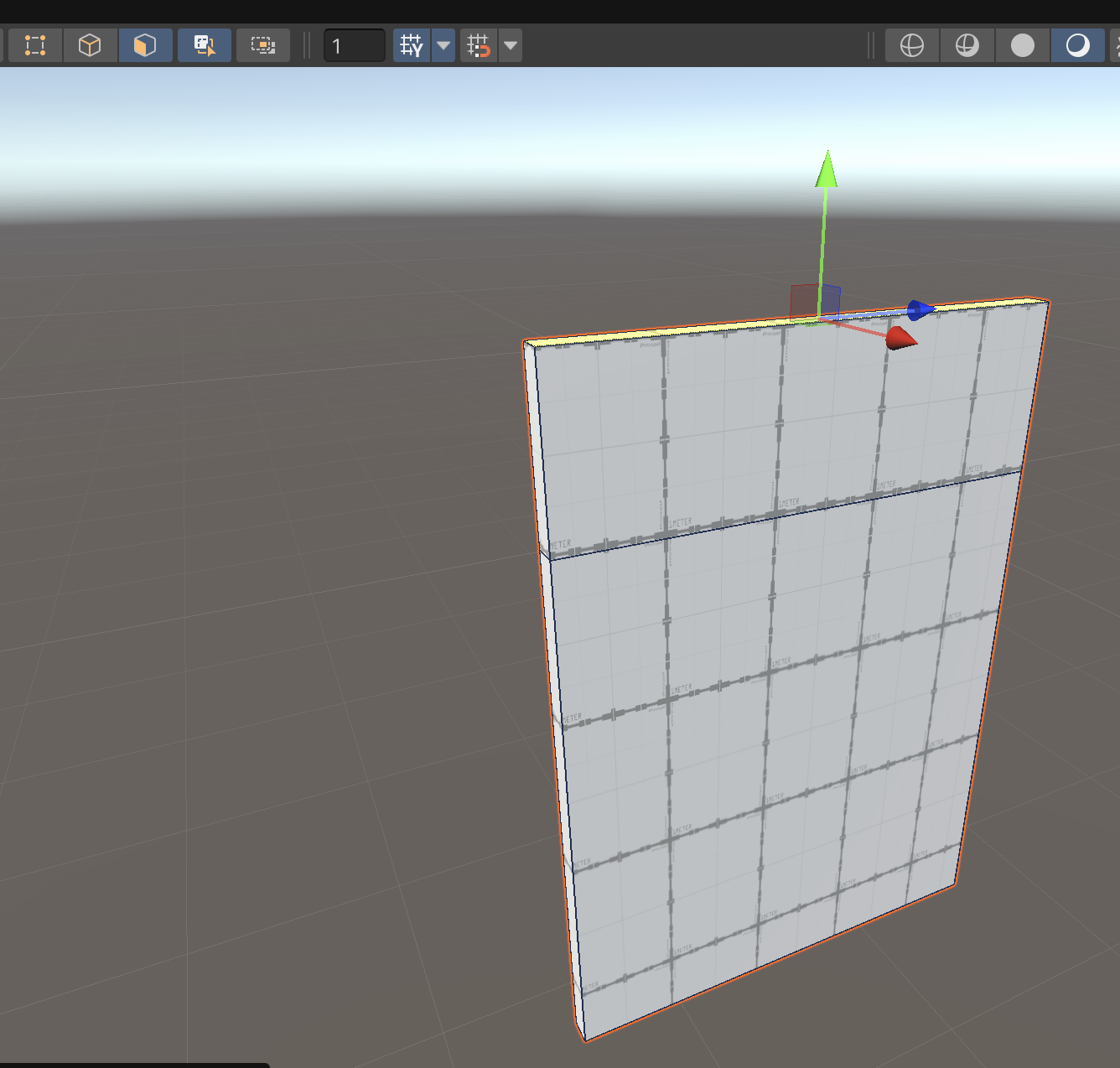
2. Multi-select two parallel edges on opposite ends of your wall.
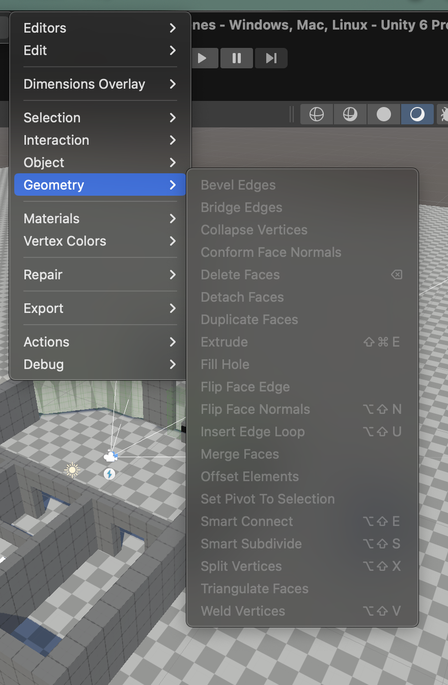
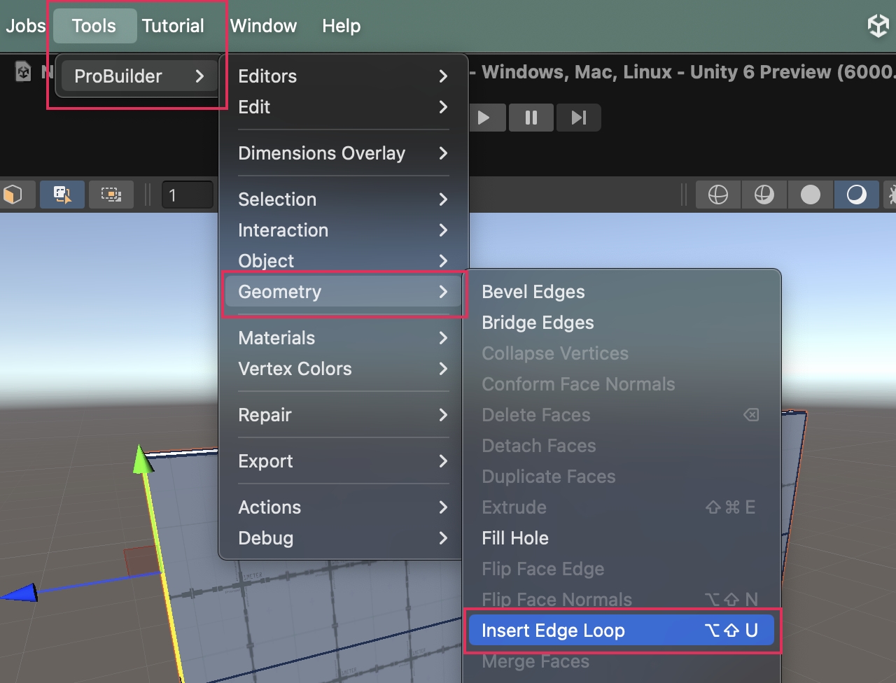
3. Select Tools > ProBuilder > Geometry > Insert Edge Loop to insert a new edge loop horizontally around your model, splitting the edges you selected in to and continuing until it forms a complete loop.
Note: Alternatively you can use the context window by right clicking and selecting Insert Edge Loop.
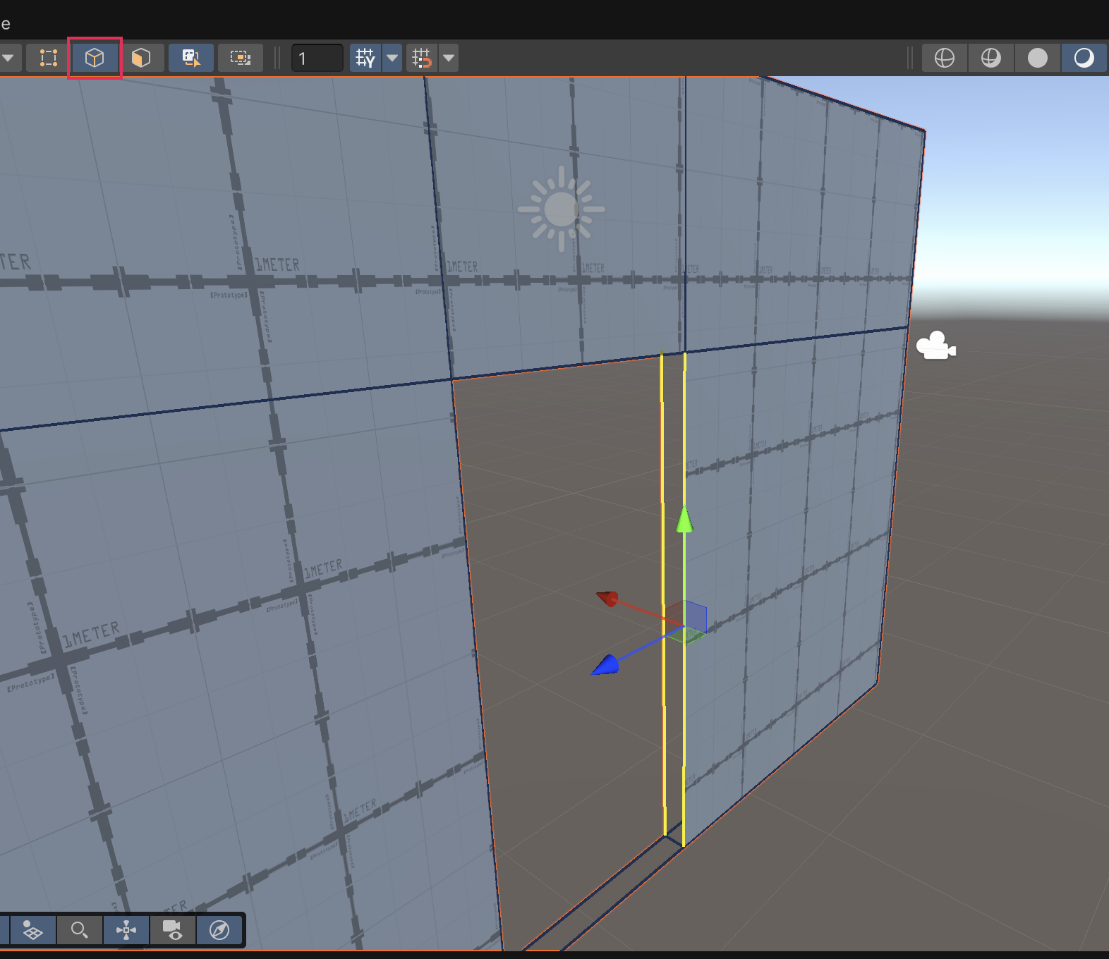
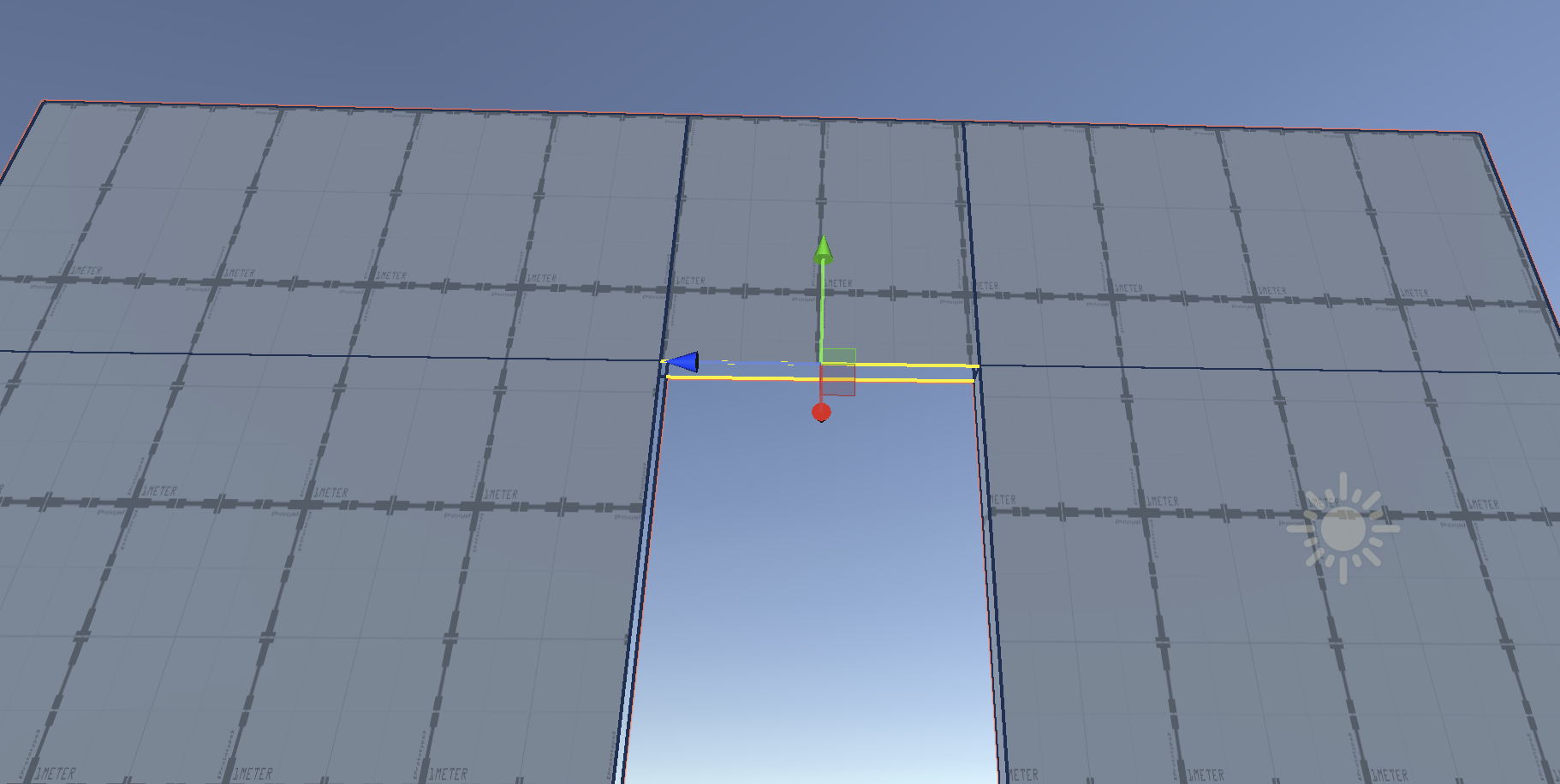
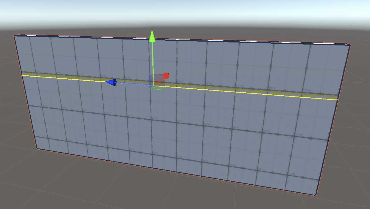
4. In the Scene view, make sure your new edge loop is selected and move it up or down, then left-click to define the height of your door.
5. Multi-select the front facing edge from the new edge loop you created and the parallel edge from the bottom of the wall.
6. In the ProBuilder window, select Insert Edge Loop.
7. In the Scene view, make sure your new edge loop is selected and move it to where you want the right side of your door to be.
8. Multi-select the left edge of the horizontal loop you created earlier and the parallel edge from the bottom of the wall.

9. In the ProBuilder window, select Insert Edge Loop.
10. In the Scene view, make sure your new edge loop is selected and move it to where you want the left side of your door to be.
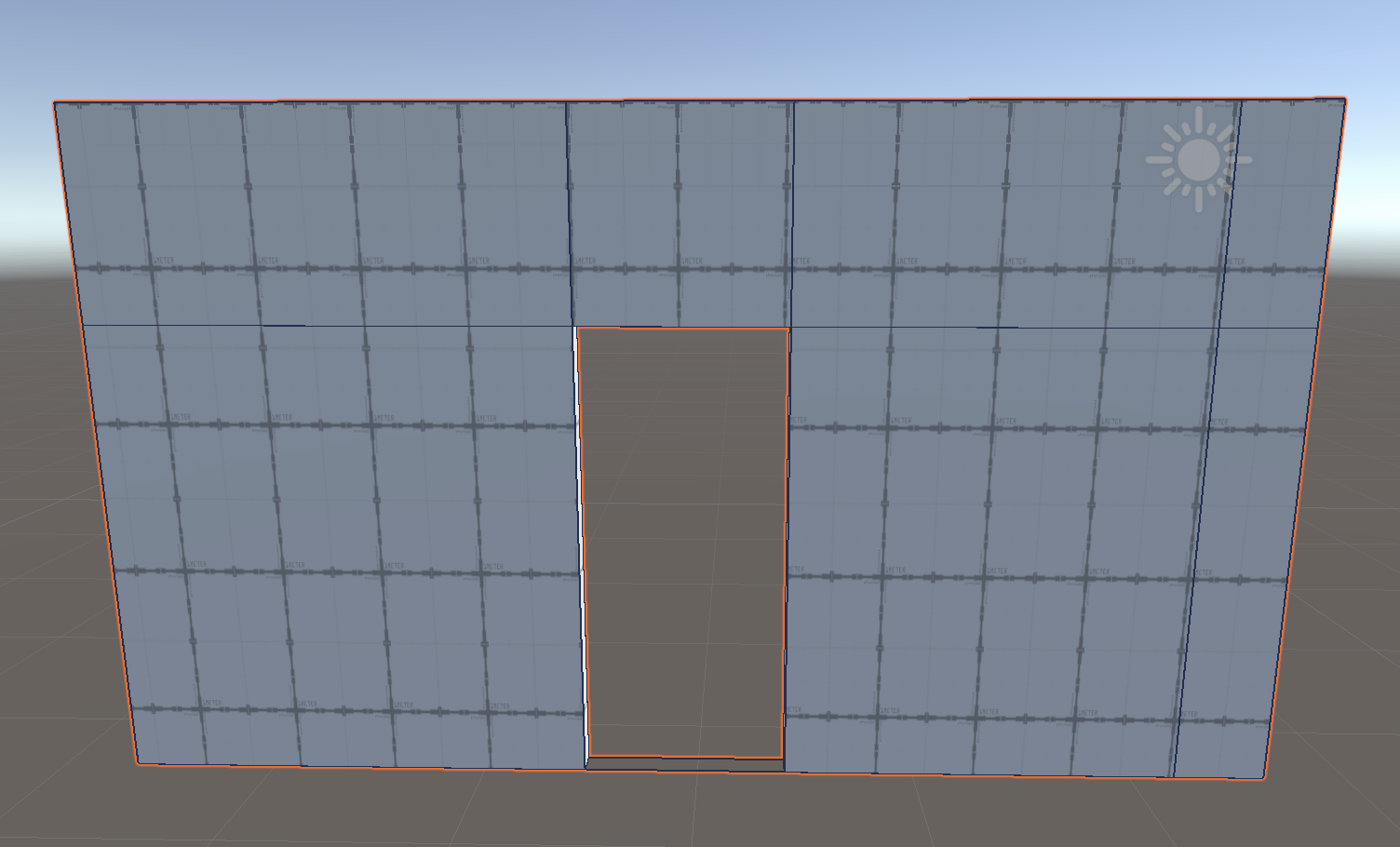
You should now have a door shaped face, similar to what you created before.
11. Now you just need to complete the same process you used before — delete the two faces and bridge the empty sides. If you’ve forgotten how to do this, refer back to the previous steps.
Extend your learning
Did you notice that this door could also easily become a window just by adding one more edge loop? If you want to try this out, just select two vertical edges and use the Insert Edge Loop function.
12. Set Collider and Set Trigger
You can turn any ProBuilder mesh into a Collider or a Trigger. This can be incredibly useful when prototyping an experience!
By default, ProBuilder meshes have a Collider attached to them. This means that a character controller would collide with the walls you created. But if you want invisible Colliders or invisible Triggers, you can use the Set Collider or Set Trigger functions in ProBuilder. Great use cases for these would be to stop users from moving outside of the experience/game area or to sense when a user moves into a new zone of an experience.
Note: Make sure that you have a character controller or player movement set up to test this. If you’re working on the Unity project you set up for your independent project in Creative Core: Prototyping, you’ll have this already.
Test out adding Colliders and triggers to your walls:
1. Choose one of your walls to work on first.
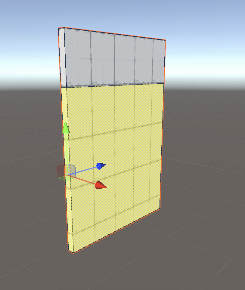
2. In the Scene view, with Object Selection enabled, select the wall.
3. In the ProBuilder window, select Set Collider. Notice how your wall has changed color and opacity.
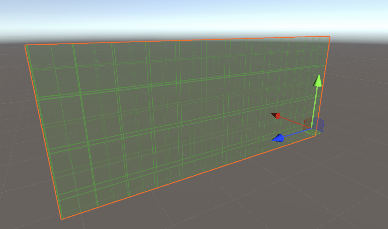
The Collider is now ready to test using a character controller.
4. In the Scene view, select the other wall.
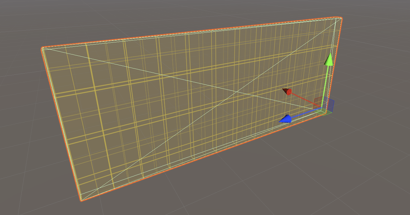
5. Select Tools > ProBuilder > Object > Set Trigger.Notice how your wall has changed color and opacity.
6. You can now use a script to detect when a character controller collides with this wall. If you’re using the custom scripts created for Creative Core: Prototyping, review how to detect these collisions using the OnTriggerEvent custom script.
13. Apply materials using ProBuilder tools
ProBuilder has tools to make it easy to apply materials so you can customize the environments that you create for your prototype with Probuilder.
You can:
- Set a quick Material, which can be applied using a button or shortcut.
- Create a Material Palette to organize multiple Materials and prototype more efficiently.
- Apply a Material to an object or just a single face.
14. Next steps
Now that you’ve practiced the ProBuilder basics in the example project, you’re ready to use your new skills to enhance your prototype. Remember, if you want to explore other uses for ProBuilder and the functionality that it offers, its documentation is a great place to start.