
UModeler X : Get started with UV Editing
Tutorial
Beginner
+10XP
30 mins
Unity Technologies
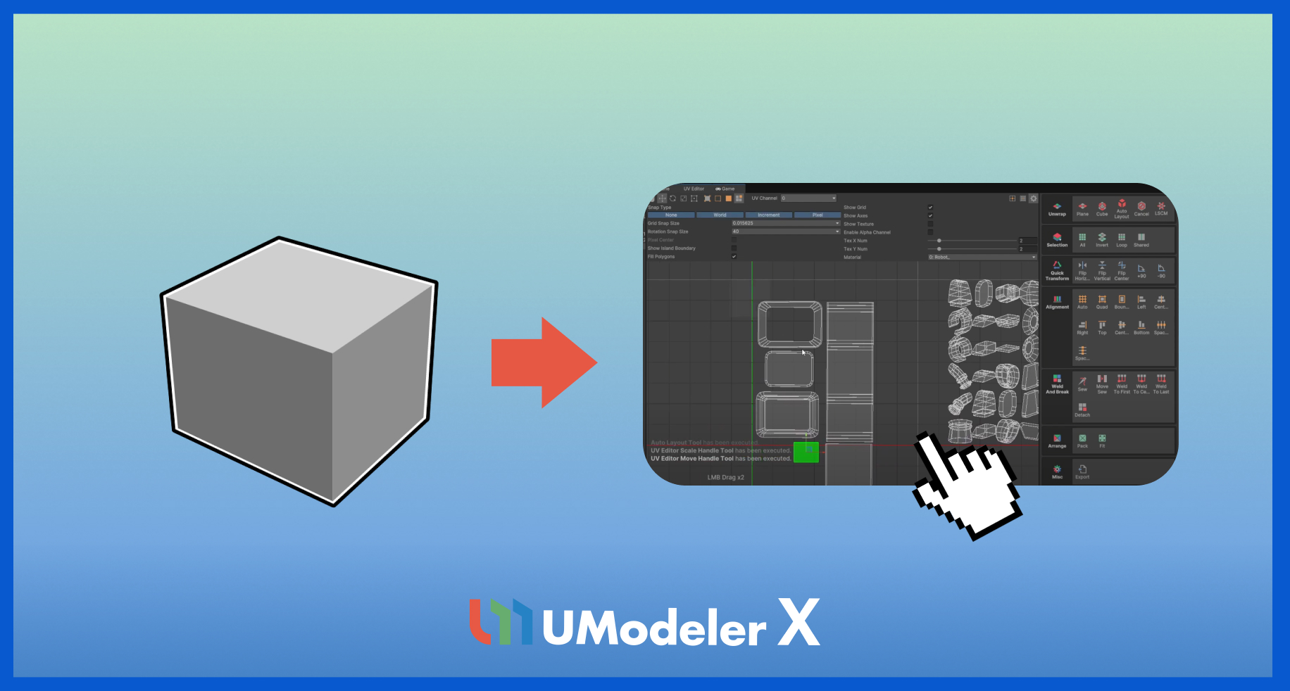
This tutorial guides you through the basics of UV editing within UModeler X. It covers opening the UV Editor, selecting faces, unwrapping, and placing UVs in texture space. It also explains how to avoid overlapping and use editing tools to refine UVs.
Resources
1. Overview
This tutorial guides you through the basics of UV editing within UModeler X. It covers opening the UV Editor, selecting faces, unwrapping, and placing UVs in texture space. It also explains how to avoid overlapping and use editing tools to refine UVs.
UVs are coordinates that define how a 2D texture is mapped onto the surface of a 3D model. They determine which part of the texture image is applied to each face of the geometry.
2. Enter the UV Editor
Before you can use the UV Editor, you need to set up an object to edit. To create an object and enter the UV Editor, follow these instructions:
1. Enter Modeling Mode and create a cube.
2. Switch to Face Selection Mode and enable Backface Selection so that back-facing polygons can also be selected.
3. After selecting the desired faces, select the UV Editor button on the right panel to enter the UV Editor.
Now, you can edit the UV map of the selected faces within the UV Editor.
3. Explore the UV Editor toolbar
UModeler UV Editor UI guide
The UV Editor allows you to efficiently edit and organize UVs.
Understanding each section will help you work faster and more accurately.
Toolbar overview
The toolbar contains tools for navigation, transform gizmos, UV element selection, and pivot control.
After selecting a UV element, you can move, rotate, or scale it using transform gizmos.
- Hand Tool (Q): Click and drag to move the view. You can also use middle-click drag without switching tools.
- Move (W): Move selected UV elements.
- Rotate (E): Rotate selected UV elements.
- Scale (R): Scale selected UV elements.
- Rectangle (T): Resize using a rectangular handle for more precise control.
UV element selection
Before you use transform or edit tools, you must select the UV elements you want to modify.
When a selection tool is active, click and drag to create a selection area - elements within or crossing it will be selected.
- UV Vertex: Select vertices.
- UV Edge: Select edges.
- UV Face: Select polygons.
- UV Island: Select connected UV elements.
Cursor and Pivot
The cursor defines a reference point in the UV Editor.
It’s mainly used as a center point for rotation or scaling and can be moved by clicking and dragging.
Gizmo Mode switching
Gizmo Mode switches between the Pivot and Center modes each time the Gizmo Mode button is selected.
- Pivot: Uses the position of the last selected UV element.
- Center: Uses the center (average position) of all selected UV elements.
Settings
The Settings area allows you to adjust the UV Editor environment.
You can control the grid, texture display, snapping units, and more for precise editing.
4. UV Editor settings area
The UV Editor settings area allows you to adjust various settings related to UV editing.
By fine-tuning options such as snapping, grid display, and texture visibility, you can create a more precise and efficient UV editing environment.
Snap Type
Snap Type defines how snapping is applied when moving, rotating, or scaling UV elements.
Snapping helps you accurately position UVs based on fixed points or angles, enhancing precision during editing.
- None: Disables snapping.
- World: Snaps UV vertices to the editor’s grid.
Grid Snap Size
Grid Snap Size sets the grid interval used for snapping when moving, rotating, or scaling elements. Grid Interval refers to the spacing between grid lines.
It defines the distance from one grid line to the next and determines how finely or coarsely objects or UVs can be aligned.
Smaller values allow finer control, while larger values create broader snapping steps.
Display options
The Display options control various visual elements displayed in the workspace:
- Show Island Boundary: Displays bounding boxes for UV islands.
- Fill Polygons: Shows UV faces as semi-transparent. This Makes overlapping UVs easier to distinguish through transparency differences.
- Show Grid: Displays the grid in the workspace.
- Show Axes: Displays U and V axes (corresponding to X/Y).
- Show Texture: Displays textures assigned in the Material settings.
- Enable Alpha Channel: Excludes transparent (alpha) areas of the texture from display.
Texture repetition
Texture repetition specifies how many times the material texture is repeated in the workspace.
- Tex X Num: Sets horizontal texture repetitions.
- Tex Y Num: Sets vertical texture repetitions.
This helps preview tiled or patterned textures more easily.
Material display
The Material display area is a key part of the UV editing environment, designed to provide clear visual feedback and precise control from snapping to texture display.
- Material: Displays only UV elements assigned with the current material.
- All: Displays all UV elements regardless of material assignment.
5. Exploring the UV Tool area
At the bottom of the UV Editor, you’ll find several tool groups for unwrapping, selecting, aligning, and packing UV elements.
Each group supports different stages of the UV editing process, improving workflow efficiency.
Unwrap group
The Unwrap Group provides tools for unwrapping and arranging UVs easily.
- Plane: Unwraps UVs based on a flat projection.
- Cube: Unwraps UVs using a cube projection.
- Auto Layout: Automatically arranges selected UVs.
- Cancel: Cancels the current unwrapping operation.
- LSCM: Uses the Least Squares Conformal Map algorithm for natural unwrapping.
- Pelt: Unwraps organic shapes smoothly using the Pelt method.
6. Next steps
In the next tutorial, you’ll learn how to paint your game assets in Unity.