Lesson 3.2 - Creating Props with ProBuilder
Tutorial
·
Beginner
·
+10XP
·
60 mins
·
(395)
Unity Technologies
In this lesson, you’ll learn more about ProBuilder by modeling a traffic cone for use in the set. In the process, you’ll learn about creating shapes, extruding, adding edge loops, and using Materials to make the cone more detailed and realistic.
Modeling in Probuilder is a useful skill because it saves you the time of having to model an object in a separate DCC — and it means you don’t have to worry about import/export settings in Unity.
Languages available:
1. Lesson Overview
2. Making the Cone Shape
Recall what we've learned about working from a reference. An image of a traffic cone reference is provided below, but we must also account for the scale of the cone relative to other props in the Scene.
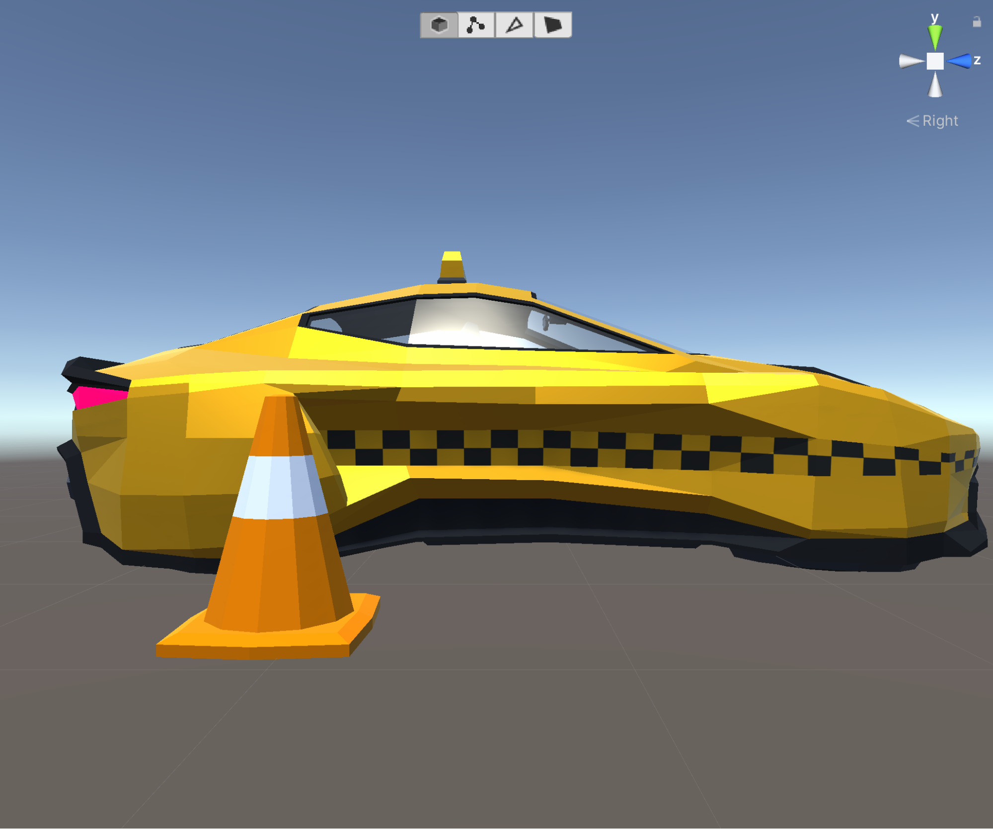
1. Drag the Taxi Prefab found in the Vehicles folder into our Scene to provide a sense of how large the traffic cone should be (Figure 01).
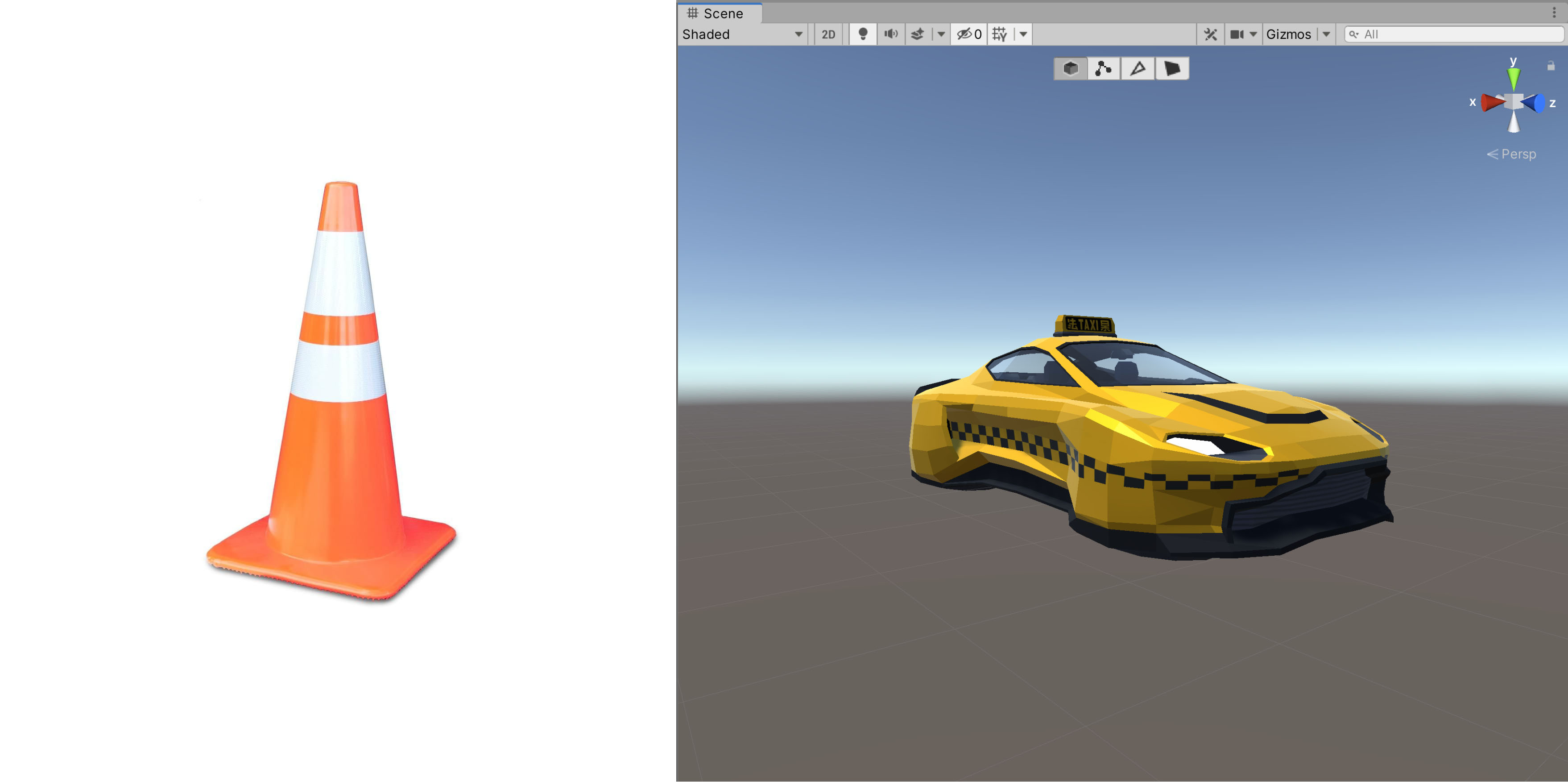
Our cone should be about a third of the height of the Taxi. With our scale reference in place, we're ready to start modelling.
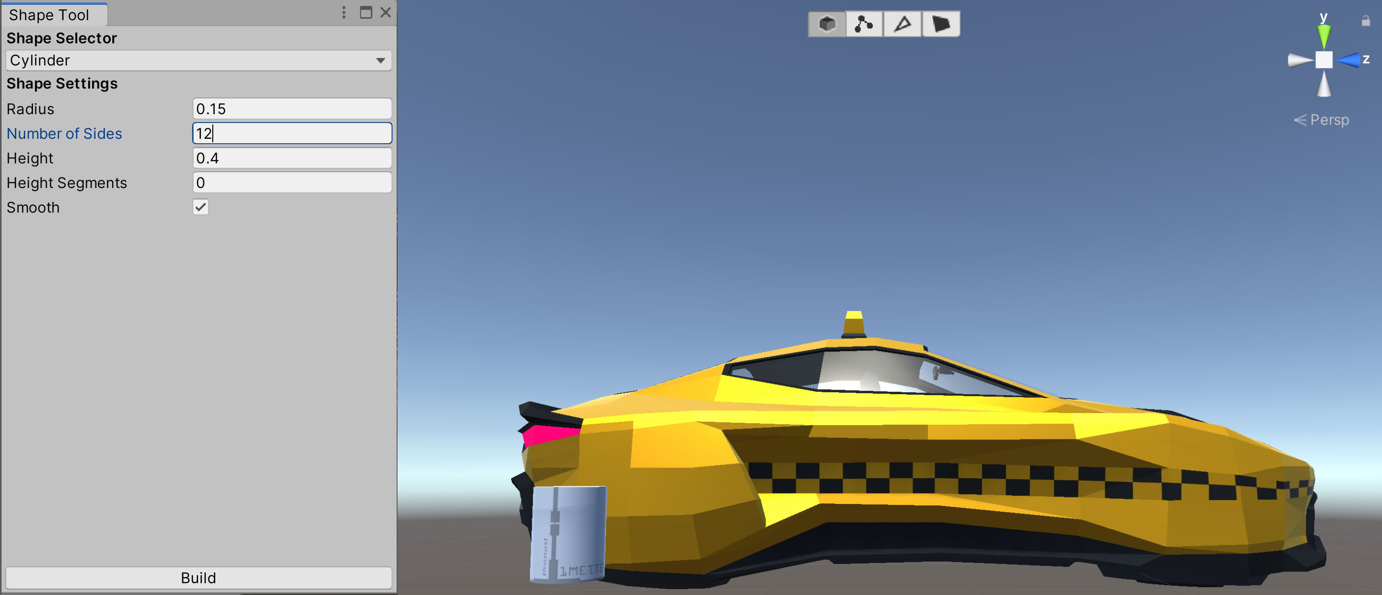
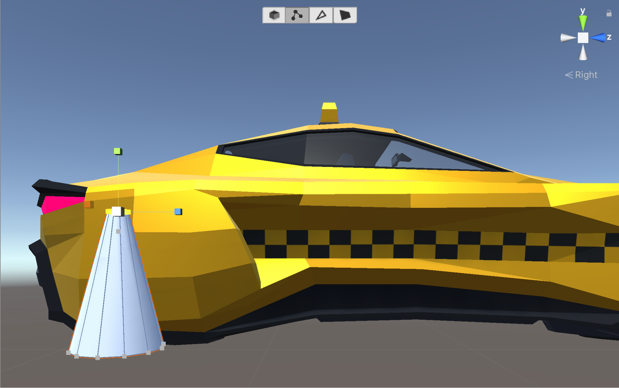
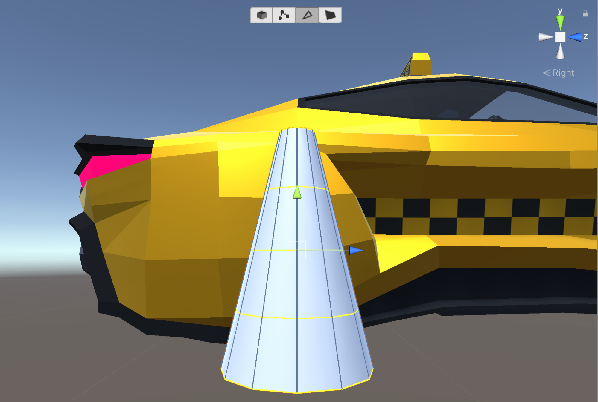
2. Alt + left-click (in Icon mode) the New Shape Tool button in the Probuilder window. If the window is closed, remember you can access it through the top menu Tools > ProBuilder > ProBuilder Window. This tool can also be accessed at any time by pressing Ctrl + Shift + K. Select the Cylinder shape, and adjust the Radius and Height values to about a third of the reference prop's height, set the Number of Sides value to 12 and ensure Smooth is unchecked. Click Build to create the Cylinder. To assist with obtaining the right scale, click on either the X or Z arrows on the gizmo in the upper-right to set the Scene view camera to look straight down the X or Z axis, allowing you to view the Cylinder and Taxi in profile (Figure 02).
3. Enter Object Mode to reposition the Cylinder to a viewing angle comfortable for you.
Next, we want to create a pointed top to create a general cone shape.
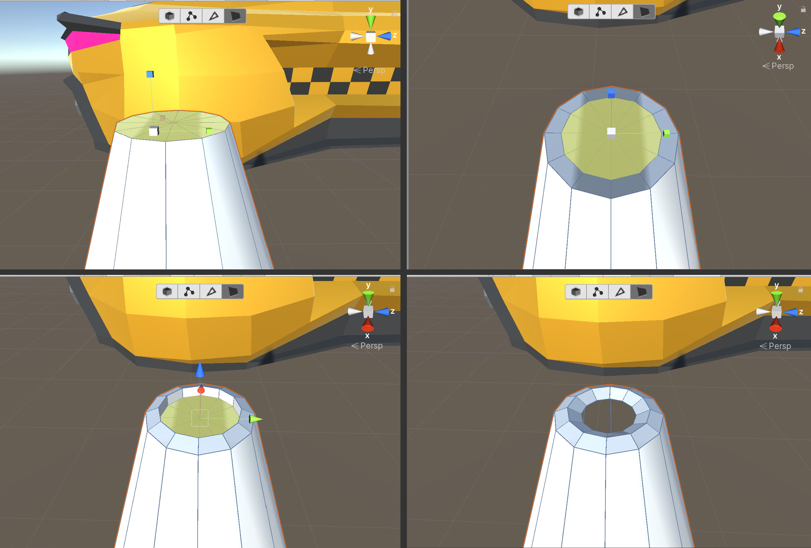
4. Enter Vertex Mode and enable the Select Hidden Tool in ProBuilder (Figure 03).
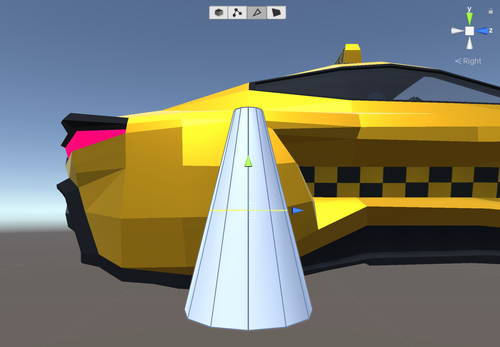
5. Select all the top vertices by left-clicking and dragging a box over them. Using the scale gizmo, uniformly scale them down to create a slightly pointed top for the cone (Figure 04).
3. Extruding the Inset at the Top of the Cone
We can build up surfaces, much like when sculpting, using a combination of the Extrude tool and basic transformations, such as Scale and Rotate. We'll do this to round out the top of the cone and create an inset.
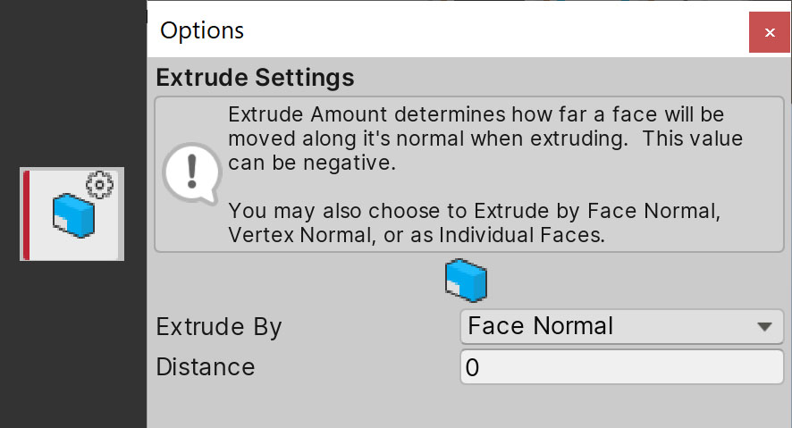
1. In Face mode, select the top faces of the cone, then Alt + left-click on the Extrude tool. In the Tool Options menu, leave Distance set to 0 before extruding. Alternatively, we can more quickly access the Extrude tool with Ctrl/Cmd + E (Figure 05).
2. While this doesn’t appear to have an effect, try scaling the selected faces uniformly inward. You’ll notice that our Extrude tool created a new set of faces we can work with.
3. Translate the set of faces up a little to build the surface, extrude them, then scale the faces in again. Repeat this combination of extrude, translate, and scale one more time to create a rounded peak for the cone.
4. With the center faces selected, scale and translate them down to create an inset. Next, delete these faces by clicking backspace to create a hole at the top of the cone (Figure 06).
4. Adding Edge Loops for Detail
Edge Loops are a series of continuous vertical edges around a model. Edge Rings are perpendicular to Edge Loops, and are a series of continuous horizontal edges around a model that take on the shape of a ring. ProBuilder displays both of them in yellow. We have two Edge Rings by default, one at the bottom of the cone and one at the top. Additional Edge Loops and Rings provide us with more faces to manipulate on an object. In our case, these enable us to create the "ring" shapes on the cone.

First, make sure that you're in Edge Mode. Since we want to create horizontal rings, we must create Edge Loops on vertical edges.
1. Select a vertical edge, then click the Select Edge Ring tool to select all of the vertical edges around that selection (so they form a loop) Then select the Insert Edge Loop tool. This creates one ring in the center (Figure 08).
2. Select another vertical edge above the Edge Ring. Then create another Edge Loop. Do this again for a horizontal edge below the Edge Ring. We should now have five Edge Loops to manipulate (Figure 09).
Next, we'll create a base for our cone.
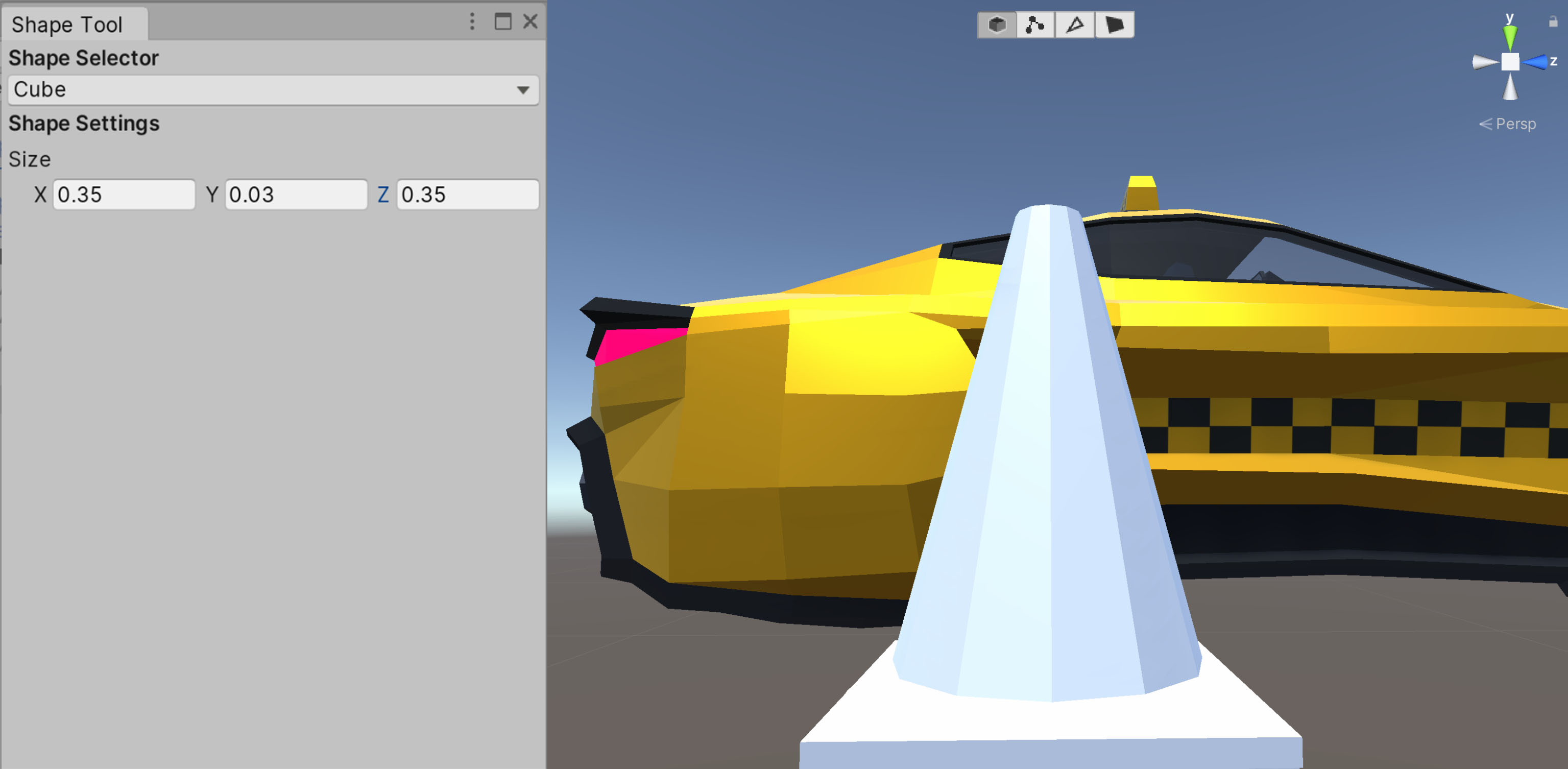
1. Click the New Shape Tool button and create a new Cube with a size of 0.35 in X and Z, and a size of 0.03 in Y. Adjust the size as needed to fit your cone. Position it below the cone so that the cone rests on the center of the Cube (Figure 10).
Let's add more detail to the base.
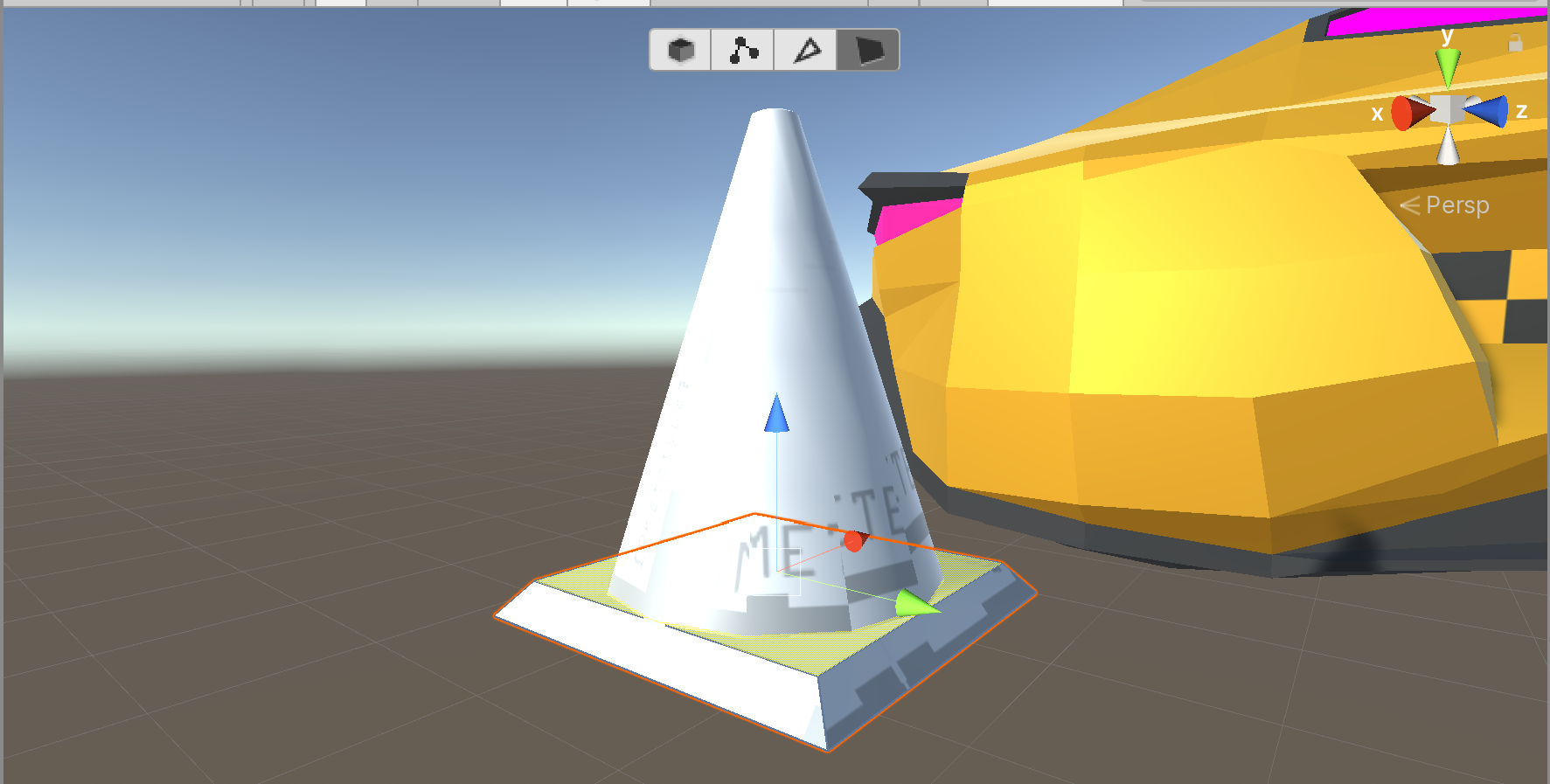
2. Return to Face Mode and select the base's top face. Extrude the face with a Distance of 0 and scale this face so its edges rest at the boundaries of the cone. With this face selected, translate it just slightly above the bottom of the cone (Figure 11).
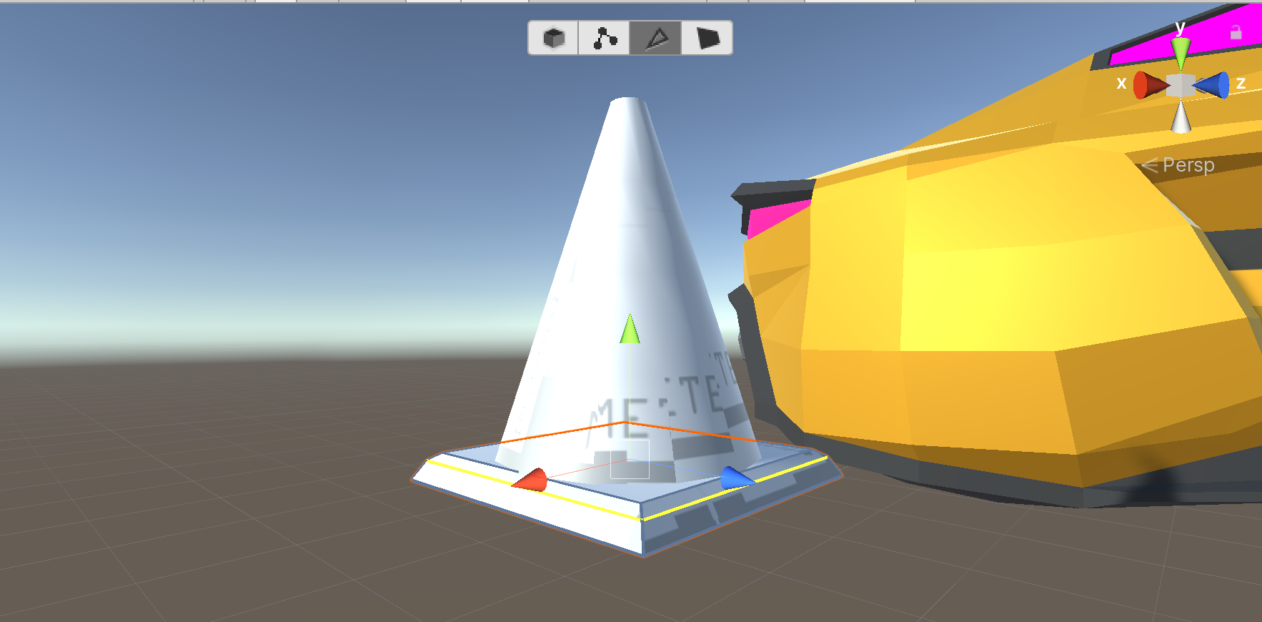
3. Create an Edge Ring around the base by selecting a vertical edge, selecting the Edge Loop, then clicking the Insert Edge Loop tool. Translate the ring up so that it’s just slightly below the top of the base (Figure 12)
Lastly, let's add some vertical Edge Loops to the base to create a more rounded appearance.
4. Shift click + select all of the horizontal edges on the base, then insert another Edge Loop. This should create neat subdivisions along the base's X and Z-axes (Figure 13).
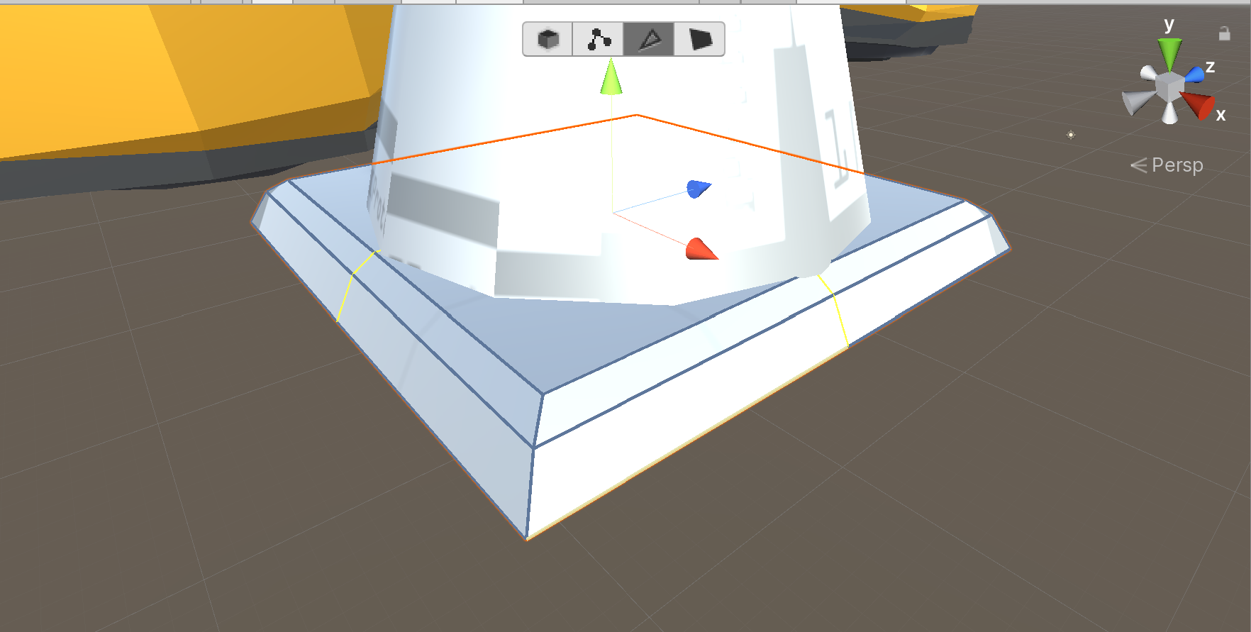
5. Uniformly scale the new Edge Loops outward to finish rounding out the base (Figure 14).
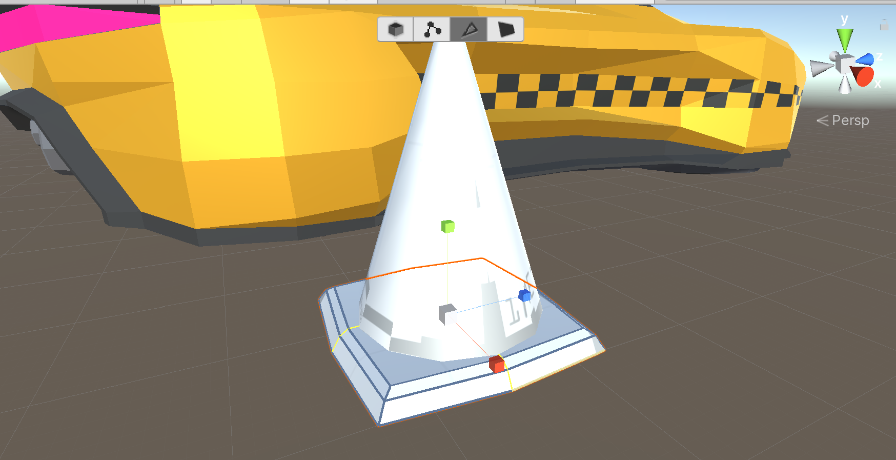
5. Adding Materials for the Cone
Now that our cone is modelled, all we need to do is give it a set of Materials so it becomes a (futuristic) traffic cone.
1. Create two Materials by right-clicking anywhere in the Project window and navigating to Create > Material.
2. Rename the Materials TrafficCone and TrafficConeStripe, one for the cone's base shape and another for its white rings (Figure 15).

3. Select the TrafficCone Material in your project, in the Inspector, under Surface Inputs navigate to Base Map and select the color picker (the box to the left). Let's select an orange color. If you have the reference image open, you can also click the eyedrop tool, hover it over the orange regions of the image, then left-click to select that color from the image (Figure 16).
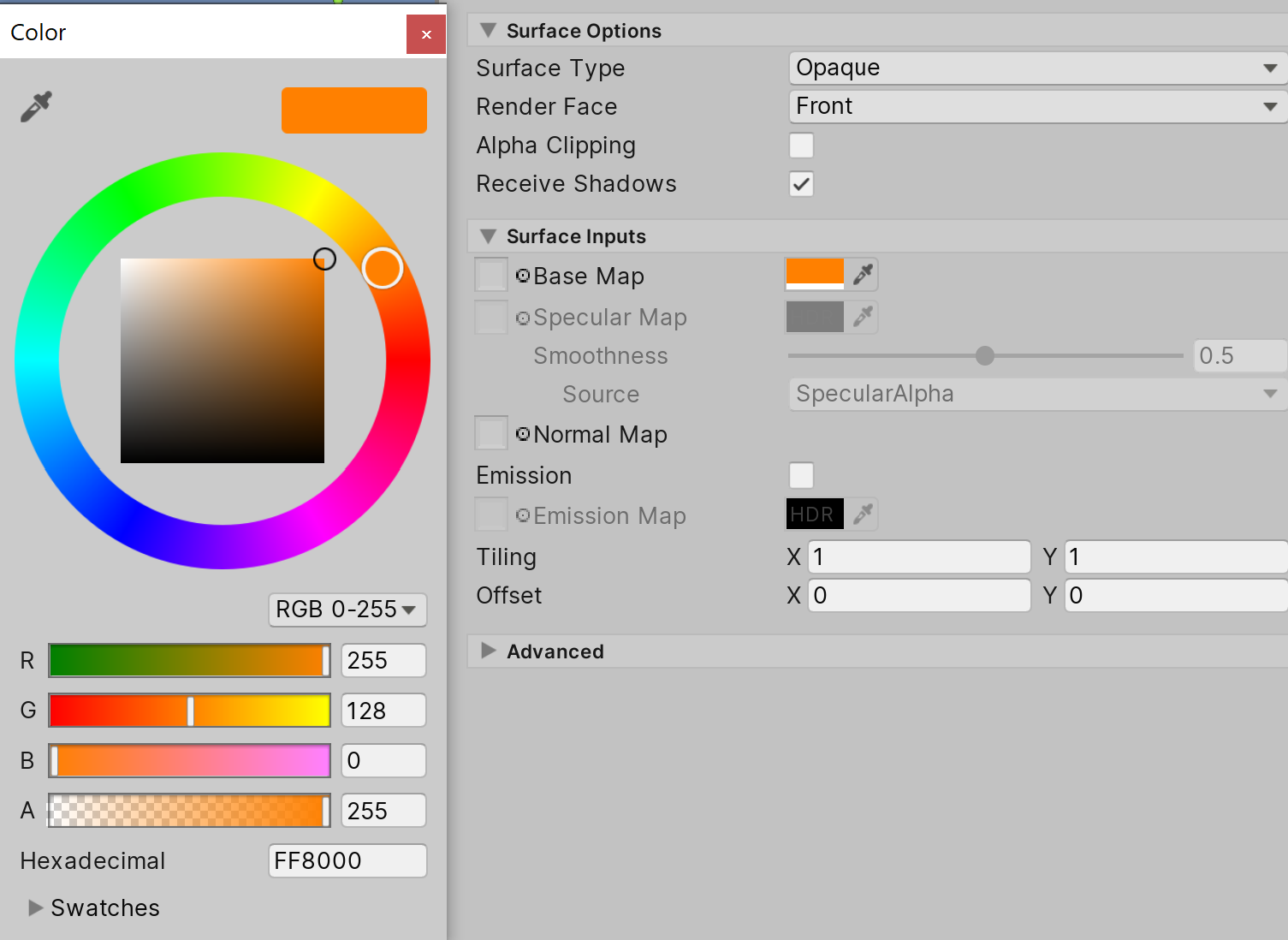
4. Repeat the same process for the TrafficConeStripe Material to get a nice bright white for the ring around the center of the cone.
Now we're ready to apply our Materials.
5. Enter Face Mode and select all the faces on the cone except for the second-to-last ring (from the top). With the faces selected, drag in the orange Material (Figure 17).
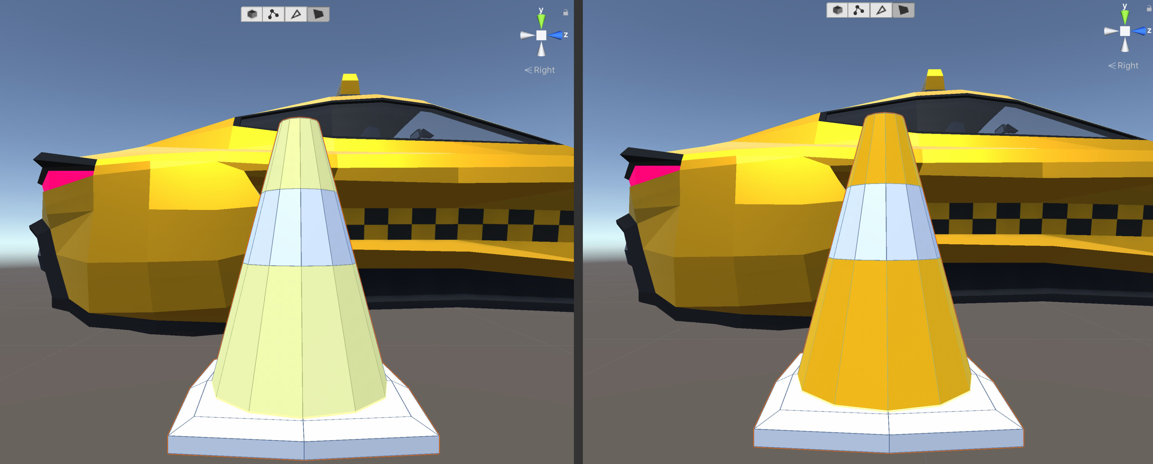
6. Repeat the same process to apply the white TrafficConeStripe Material.
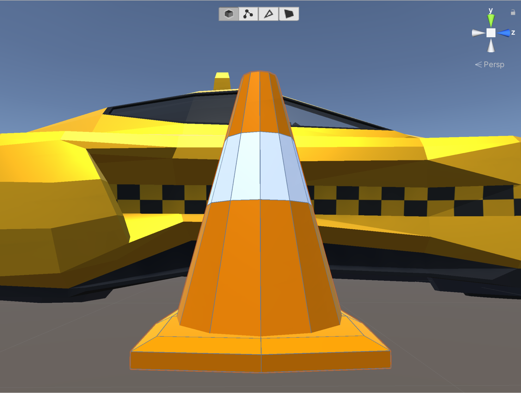
7. Now apply the orange Material to the base (Figure 18).
While our cone is finished, two more steps will make it more efficient. The first would be to consolidate our ProBuilder shapes into a single object using the Merge Objects Tool. The second would be to freeze the transforms on the merged object so that new instances of the Cone (we want to place many in our Scene) are placed at its origin and not offset by any values (Figure 19).

8. Enter Object Mode, then select both the Cylinder and the Cube (the pieces needed to construct the cone and base, respectively).
9. Select the Merge Objects Tool. This will treat the traffic cone as one object instead of several pieces (Figure 20).
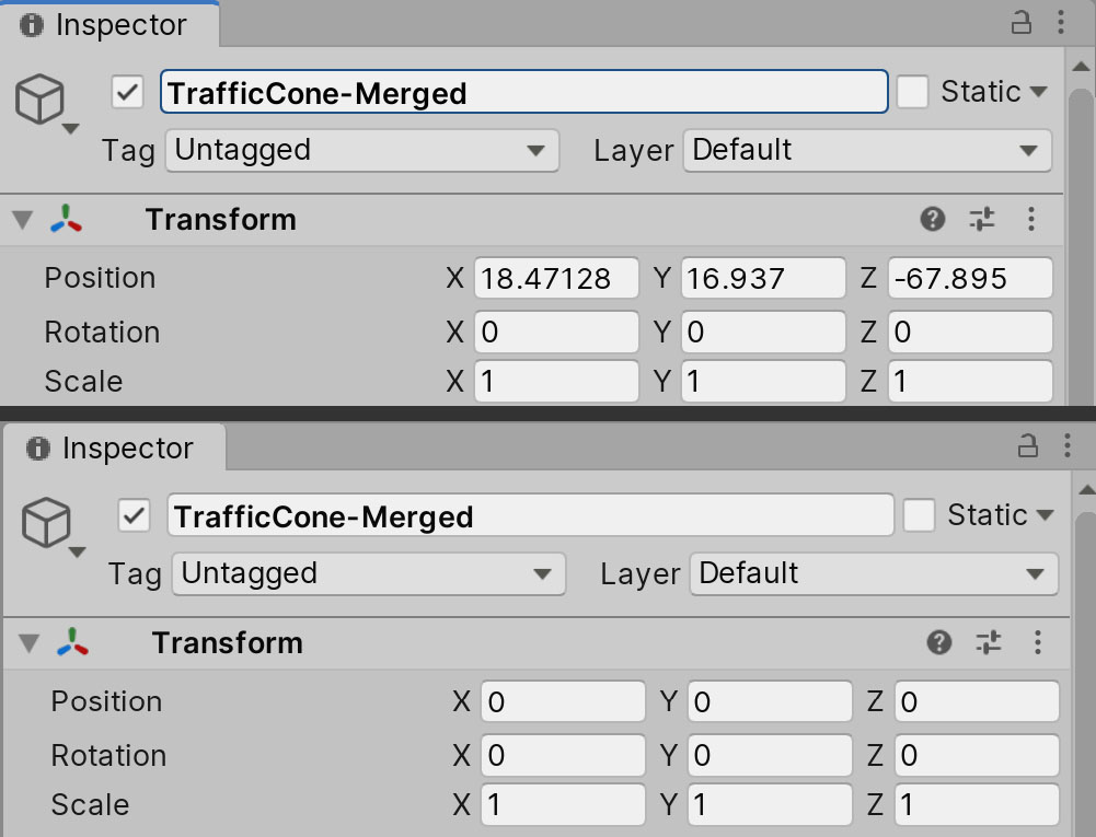
10. Select the cone then click the Center Pivot tool. Then, set the Transform positions of the object to 0, 0, 0. Finally, select the Freeze Transform function.This will be useful in the event we want to create a Prefab out of our traffic cone (which we should), making each instance appear in the Scene as it should without any additional offsets (Figure 21).
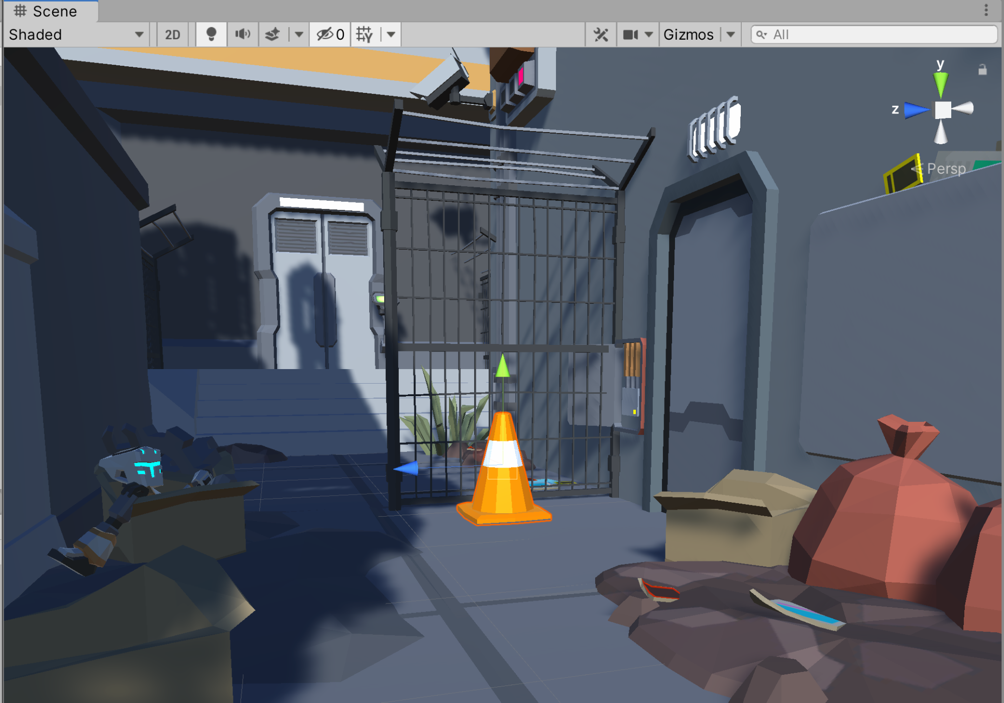
11. Lastly, place the traffic cone in your Scene and delete the Taxi prefab we used as a scale reference (Figure 22).
6. Recap
Here we've expanded upon our knowledge of ProBuilder by using it to create a new prop. We have the flexibility to create many new objects with ProBuilder to add even more life to our Scenes. In the next lesson, we'll build upon our knowledge of lighting to boost mood and cohesion in our Scene.